X-ray phase imaging method

a phase imaging and phase imaging technology, applied in the direction of material analysis using wave/particle radiation, instruments, applications, etc., can solve the problem of difficult to see phase-contrast images, and achieve the effect of suppressing phase-contrast images

Active Publication Date: 2021-11-23
SHIMADZU CORP
View PDF4 Cites 0 Cited by
  • Summary
  • Abstract
  • Description
  • Claims
  • Application Information

AI Technical Summary

Benefits of technology

[0006]The present invention has been made to solve the problems newly discovered by the inventors of the present invention as described above, and an object of the present invention is to provide an X-ray phase imaging apparatus capable of suppressing a phase-contrast image from becoming difficult to see due to a gradation that occurred in the phase-contrast image.
[0008]According to the present invention, as described above, a phase-contrast image is generated based on a plurality of images acquired with a subject and an imaging system being relatively translated with each other by a moving mechanism, and a gradation that occurred along an orthogonal direction to the translation direction as viewed from the optical axis direction of the X-rays in the phase-contrast image is corrected based on the distribution state of the gradation. With this, it is possible to remove the gradation that occurred along the orthogonal direction to the translation direction as viewed from the optical axis direction of the X-rays in the phase-contrast image. Therefore, it is possible to suppress the phase-contrast image from becoming difficult to see due to the gradation that occurred in the phase-contrast image.

Problems solved by technology

Here, although not specifically described in the above-described Japanese Unexamined Patent Application Publication No. 2017-44603, the inventors of the present application have newly discovered that in the case of generating a phase-contrast image based on a plurality of images acquired while relatively translating the subject and the imaging system as in the radiological examination apparatus described in the above-described Japanese Unexamined Patent Application Publication No. 2017-44603, there is a problem (issue) that the phase-contrast image becomes difficult to see because a gradation (gradual change in color tone, brightness, etc.) that occurred along a direction orthogonal to the translation direction as viewed from the optical axis direction of the X-rays in the phase-contrast image.

Method used


Image

  • X-ray phase imaging method
  • X-ray phase imaging method
  • X-ray phase imaging method

Examples


Embodiment Construction

[0031]Hereinafter, an embodiment in which the present invention is embodied will be described with reference to the attached drawings.

[0032]Referring to FIG. 1 to FIG. 17, the configuration of an X-ray phase imaging apparatus 100 according to an embodiment of the present invention will be described.

Configuration of X-Ray Phase Imaging Apparatus

[0033]First, referring to FIG. 1, the configuration of the X-ray phase imaging apparatus 100 according to this embodiment will be described.

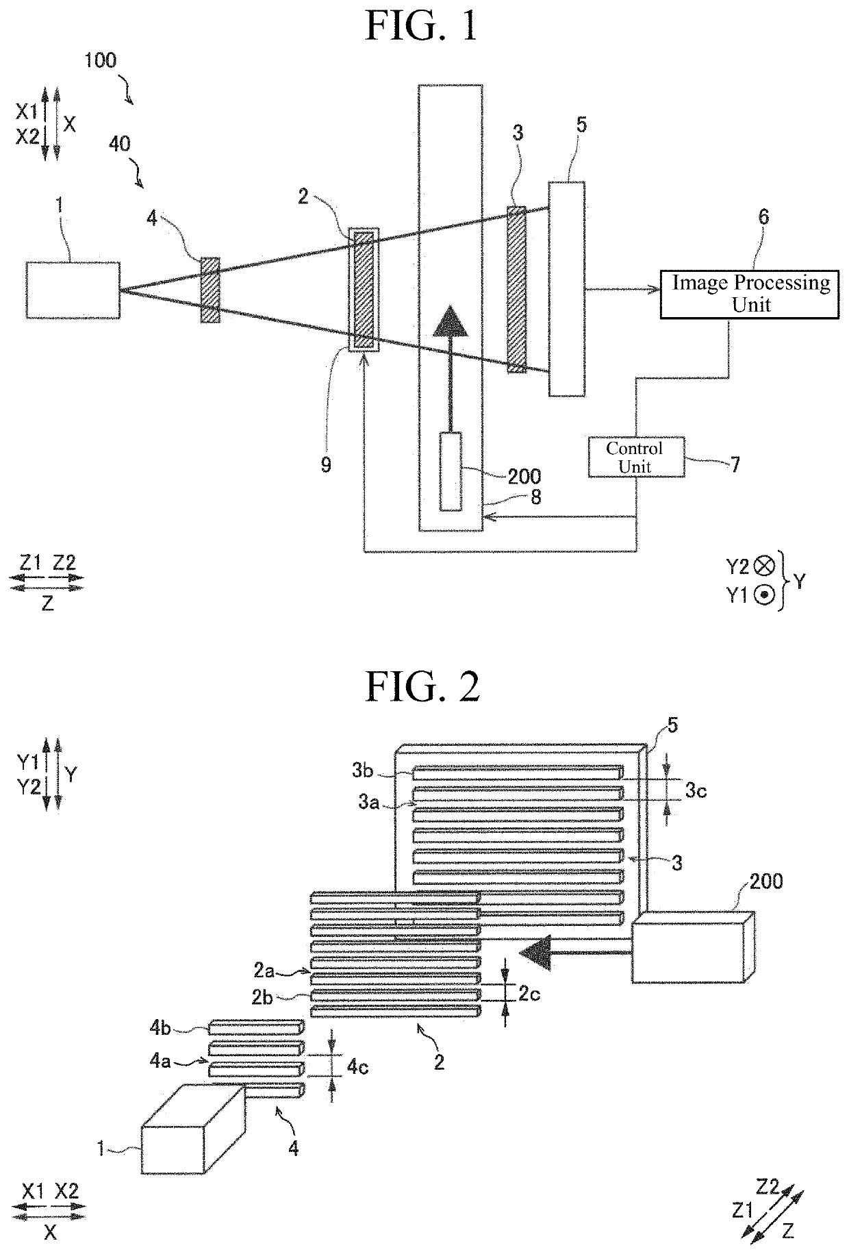
[0034]As shown in FIG. 1, the X-ray phase imaging apparatus 100 is a device for imaging an inside of a subject 200 by utilizing a Talbot effect. The X-ray phase imaging apparatus 100 can be used for imaging the inside of the subject 200 as an object, for example, in non-destructive inspection applications.

[0035]FIG. 1 is a schematic diagram of the X-ray phase imaging apparatus 100 as viewed from the Y-direction. As shown in FIG. 1, the X-ray phase imaging apparatus 100 is provided with an X-ray source 1, a...


PUM

PropertyMeasurementUnit
phase-aaaaaaaaaa
phaseaaaaaaaaaa
widthaaaaaaaaaa

Abstract

An X-ray phase imaging method includes a step of correcting a gradation that occurred along an orthogonal direction to a translation direction as viewed from an optical axis direction of X-rays in a phase-contrast image based on a distribution state of the gradation.

Description

CROSS-REFERENCE TO RELATED APPLICATIONS[0001]The related application number JP2019-216750, entitled “X-ray phase imaging apparatus”, filed on Nov. 29, 2019, invented by Satoshi Sano, Koichi Tanabe, Yukihisa Wada, Satoshi Tokuda, Akira Horiba, and Naoki Morimoto, upon which this patent application is based is hereby incorporated by reference.BACKGROUND OF THE INVENTIONField of the Invention[0002]The present invention relates to an X-ray phase imaging method.Description of the Background Art[0003]Conventionally, an X-ray phase imaging apparatus is known in which a subject is imaged while relatively translating the subject and an imaging system. Such an apparatus is disclosed in, for example, Japanese Unexamined Patent Application Publication No. 2017-44603.[0004]In the above-described Japanese Unexamined Patent Application Publication No. 2017-44603, a radiological examination apparatus (X-ray phase imaging apparatus) is disclosed in which a radiation source unit, a grating group, a d...

Claims


Application Information

Patent Timeline
Patent Type & Authority Patents(United States)
IPC IPC(8): G01N23/041A61B6/00
CPCA61B6/484A61B6/4035A61B6/463A61B6/5205A61B6/4476A61B6/5229A61B6/4291
Inventor SANO, SATOSHITANABE, KOICHIWADA, YUKIHISATOKUDA, SATOSHIHORIBA, AKIRAMORIMOTO, NAOKI
Owner SHIMADZU CORP
Why Eureka
Try Eureka