Three-dimensional printing apparatus

a three-dimensional printing and printing technology, applied in the direction of manufacturing tools, manufacturing driving means, additive manufacturing, etc., can solve problems such as unsatisfactory release performance, and achieve the effect of improving the release performance of workpieces

Active Publication Date: 2022-01-11
YOUNG OPTICS
View PDF6 Cites 0 Cited by
  • Summary
  • Abstract
  • Description
  • Claims
  • Application Information

AI Technical Summary

Benefits of technology

[0005]According to another aspect of the present disclosure, a three-dimensional printing apparatus includes a light-transmissive plate having a first surface, a platform, a support frame, a supporting seat and a rotating shaft. The platform is disposed above the light-transmissive plate, and the support frame is disposed under the light-transmissive plate. The supporting seat is disposed under the support frame and defines an accommodation space under the light-transmissive plate for accommodating an image light source. The rotating shaft pivots on a point inside or on the support frame and has a shaft center, and the shaft center is disposed under an extending plane extending from the first surface. In the above aspect, since the shaft center is disposed under the extending plane extending from the first surface, when the support frame rotates about the rotating shaft, two components of forces may respectively act on the workpiece in different directions to improve release performance of the workpiece.

Problems solved by technology

Such drag force applied in the normal direction may damage the workpiece and result in an unsatisfactory release performance.

Method used


Image

  • Three-dimensional printing apparatus
  • Three-dimensional printing apparatus
  • Three-dimensional printing apparatus

Examples


Embodiment Construction

[0009]In the following detailed description of the preferred embodiments, directional terminology, such as “top,”“bottom,”“front,”“back,” etcetera, is used with reference to the orientation of the Figure(s) being described. The components of the invention can be positioned in a number of different orientations. As such, the directional terminology is used for purposes of illustration and is in no way limiting. Further, “First,”“Second,” etcetera, as used herein, are used as labels for nouns that they precede, and do not imply any type of ordering (e.g., spatial, temporal, logical, etcetera).

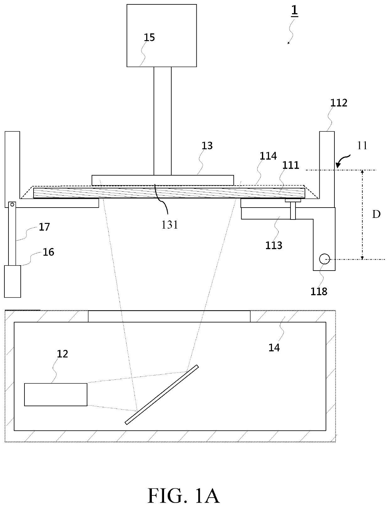
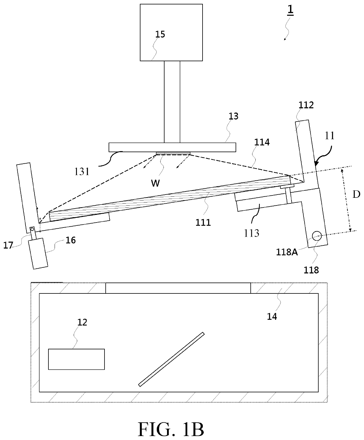
[0010]FIG. 1A and FIG. 1B illustrate a three-dimensional printing apparatus according to an embodiment of the invention, where FIG. 1A shows a state of the printing apparatus before it operates and FIG. 1B shows a state of the printing apparatus during operation. In this embodiment, the three-dimensional printing apparatus 1 includes a material tank 11, an image light source 12, a workpiece holde...


PUM

PropertyMeasurementUnit
distanceaaaaaaaaaa
transmittanceaaaaaaaaaa
distanceaaaaaaaaaa

Abstract

One embodiment of the invention provides a three-dimensional printing apparatus including a light-transmissive plate having a first surface, a platform, a support frame, a supporting seat and a rotating shaft. The platform is disposed above the light-transmissive plate, and the support frame is disposed under the light-transmissive plate. The supporting seat is disposed under the support frame and defines an accommodation space under the light-transmissive plate for accommodating an image light source. The rotating shaft pivots on a point inside or on the support frame and has a shaft center, and the shaft center is disposed under an extending plane extending from the first surface.

Description

BACKGROUND OF THE INVENTIONa. Field of the Invention[0001]The invention relates generally to a three-dimensional printing apparatus, and more particularly to a three-dimensional printing apparatus that realizes the release of a printed workpiece through rotational movement.b. Description of the Related Art[0002]In a pull-up type three-dimensional printing apparatus, a workpiece may be released and separated from a light-transmissive plate beneath the workpiece by moving the light-transmissive plate, thus allowing the printing process to proceed with a subsequent layer.[0003]In a conventional design, a rotating shaft and a light-transmissive plate are disposed in substantially the same plane. Therefore, when the light-transmissive plate rotates, an initial acceleration may be generated in a direction perpendicular to the workpiece to cause a normal drag force acting between the workpiece and the light-transmissive plate. Such drag force applied in the normal direction may damage the ...

Claims


Application Information

Patent Timeline
Patent Type & Authority Patents(United States)
IPC IPC(8): B29C64/245B29C64/227B33Y30/00B29C64/124
CPCB29C64/245B29C64/227B29C64/124B33Y30/00
Inventor TSAI, CHIEN-HSING
Owner YOUNG OPTICS
Why Eureka
Try Eureka