Barbell grips

a barbell and angled technology, applied in the field of barbell grips, can solve the problems of static (movable) gripping surfaces, inability to move, and inability to move, so as to achieve natural and effective grip, without joint stress or pain, and neutral grip

Active Publication Date: 2022-03-08
NEW GROWTH FITNESS LLC
View PDF50 Cites 2 Cited by
  • Summary
  • Abstract
  • Description
  • Claims
  • Application Information

AI Technical Summary

Benefits of technology

[0008]Embodiments of the present invention comprise, in part, a barbell grip that orients to the bar at an angle. This allows a user to perform exercises such as bench press and barbell row with a more neutral grip than previously possible using grip devices in the prior art. It provides a means to exercise without joint stress or pain during or after a workout. The grip of the present invention can be used with barbells (and other exercise devices that include a bar element) to perform exercises such as bicep curl variations, tricep extension variations, overhead presses, bench presses, and pull ups, among others. These exercises can be performed using a more natural and effective hand orientation than without the grip. The barbell grips of the present invention also allows the user to add a tremendous amount of variation to workouts by performing each selected exercise at several different user-determined hand placements and grip angles simply by moving the barbell grips across the bar to different positions and relative widths to one another, or by rotating the grips around the longitudinal axis of the bar.
[0010]The angled orientation of the grip to the bar allows the user to perform barbell exercises with a more natural grip, and the larger grip diameter helps stabilize joints and engage more muscle fibers. The barbell grip can be moved anywhere along the bar and the grips can be rotated to create the optimal grip width and angle for each individual user.
[0012]An Internal Bore that runs through the Main Body at an angle so that the grip attaches to the bar at an angle and allows a more neutral and natural grip for the user performing barbell exercises.
[0014]The Slit runs diagonal to the Internal Bore and substantially parallel to the longitudinal axis of the Main Body. This allows the barbell grip to wrap around the bar fully so that each parallel cross section of the bar is supported by the barbell grip at several points. If the Slit were to run parallel to the Internal Bore, it would be much easier for the bar to accidently slip out of the barbell grip while in use.
[0015]While in use, the Slit of each barbell grip in a matched, cooperating pair can face the same direction because the barbell grips in such a pair are not structurally identical, rather, the barbell grips in a matched pair are typically substantially symmetrical to one another but have mirrored symmetry versus identically oriented structural elements. Thus, the barbell grips can be safely used with heavy weight mounted on the bar, and with exercises where weight is held over the user's body. For example, if one Slit were to be facing the user and the other were to be facing away while performing a bench press (in which the user lays on his or her back and pushes weight above his or her chest), there would be tremendous risk the weight would cause the bar to fall through the Slit and into the user's hand, or even through the user's hand causing serious injury.

Problems solved by technology

After strength training and lifting weights for 15 years, the inventor began to experience severe joint pain and discomfort during and after workouts.
Prior art weightlifting bars that are prevalent in most gyms have serious deficiencies, including static (immovable) gripping surfaces placed either too narrow or too wide for most users.
In addition, these prior art thick grips can cause additional stress upon a user's wrist, elbow and shoulder joints, because when using them a user can no longer as easily slightly rotate their hands upon the bar to slightly ease pronation during use to at least slightly / minimally relieve such stress (albeit while also reducing the ability to lift heavier weights, or reducing the ability to endure a desired number of repetitive lifts).
While an increased diameter bar grip by itself may somewhat help to engage more muscles throughout the upper body, it still does not solve the problem of pronation and suboptimal hand placement upon a bar and it does not allow a user to comfortably perform major lifts like bench pressing and bar bell rows.
This destabilizes the grip and creates a disparity between the grips in terms of feel to the user, especially when heavy weights are in use upon the bar.
Such grips are also more prone to slipping off the bar and are difficult to align with one another with regard to angles relative to the bar.

Method used


Image

  • Barbell grips
  • Barbell grips
  • Barbell grips

Examples


Embodiment Construction

[0034]As required, detailed embodiments of the present invention are disclosed herein; however, it is to be understood that the disclosed embodiments are merely exemplary of the invention, which may be embodied in various forms. Therefore, specific structural and functional details disclosed herein are not to be interpreted as limiting, but merely as a basis for the claims and as a representative basis for teaching one skilled in the art to variously employ the present invention in virtually any appropriately detailed structure.

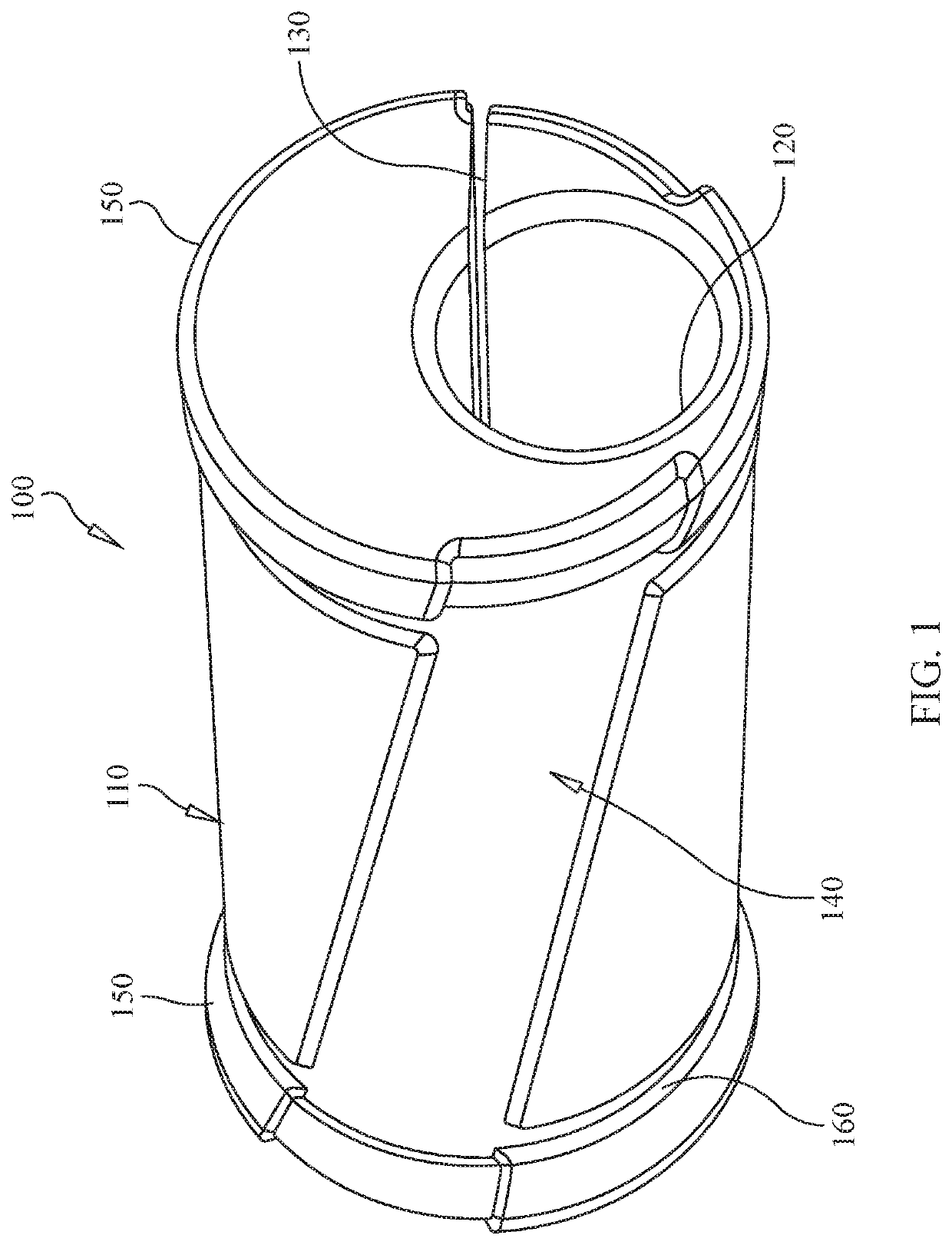
[0035]FIG. 1 is an enlarged, front, right perspective view illustrating components of an embodiment of the barbell grip 100 of the present invention. The Main Body 110 of the barbell grip 100 is substantially cylindrical in shape with a diameter optimized to allow most adults to comfortably and securely wrap their hands at least partially or substantially around the barbell grip 100 when grasping or gripping it for use. Typically, the Main Body 110 has a larg...


PUM


Abstract

A set of angled grips for attachment to a weightlifting bar, such as a barbell bar or similar device, in order to provide an optimized gripping surface for a user's hands in terms of increased friction and comfort of the grips, thickness and circumference of the grips, and ergonomic angle of each grip surface relative to the bar.

Description

CROSS REFERENCE TO RELATED APPLICATION[0001]This application claims the benefit of the prior-filed, provisional patent application, Ser. No. 62 / 800,593, filed Feb. 4, 2019.FIELD OF THE INVENTION[0002]The present invention relates to athletic equipment, and more particularly to angled barbell grips for attachment to a barbell or other weightlifting bar to provide an ergonomically optimized gripping surface for a user's hands.BACKGROUND OF THE INVENTION[0003]After strength training and lifting weights for 15 years, the inventor began to experience severe joint pain and discomfort during and after workouts. Eventually, the inventor sought help from a sports medicine chiropractor and physical therapist. Advice was provided to discontinue barbell exercises, and instead use dumb bells and weight machines. This would allow the inventor's arms to move independently of one another, and his wrist would be able to rotate to allow for a more neutral and natural grip upon a bar. The combination ...

Claims


Application Information

Patent Timeline
Patent Type & Authority Patents(United States)
IPC IPC(8): A63B21/072A63B21/00
CPCA63B21/4035A63B21/0724
Inventor LEADBETTER, MATT CHRISTOPHER
Owner NEW GROWTH FITNESS LLC
Why Eureka
Try Eureka