Ankle brace

a technology for ankles and knees, applied in the field of ankle braces, can solve the problems of unfavorable patient comfort, unfavorable patient comfort, and inability to adjust the tape, and achieve the effect of reducing the risk of injury and high utility

Active Publication Date: 2022-05-31
MCVEIGH JASON +1
View PDF4 Cites 1 Cited by
  • Summary
  • Abstract
  • Description
  • Claims
  • Application Information

AI Technical Summary

Benefits of technology

[0006]The present general inventive concept can provide, inter alia, preventative or therapeutic restraint of the normal movements of the ankle and / or foot. This includes, but is not limited to, inversion or eversion relative to the lower leg in excess of the natural limits of movement typically available to the ankle and / or foot. Typically, either to restrict an injured ankle / foot or to restrict a healthy ankle / foot to lower the risk of injury, an ankle brace should be used regularly. Ease of application, speed of application, and ease and speed of removal are vital components of an ankle brace with high utility.

Problems solved by technology

Typically, any support or restriction placed outside the shoe is provided via disposable adhesive material, commonly called athletic tape or “spat tape.” Spat tape, being a disposable adhesive material, is limited to a single use; it is not reusable.
Further, spat tape must be removed either by unwinding or cutting it off, which delays access to the ankle or foot in the event of injury and may caused an injured person to experience increased pain or discomfort due to motion during the removal process as the tape is unwound or cut off.
Further, tape may not allow for the adjustability provided by the present general inventive concept.
Also, tape may not provide for the quality of joint restriction provided by the present general inventive concept.

Method used


Image

  • Ankle brace
  • Ankle brace
  • Ankle brace

Examples


Embodiment Construction

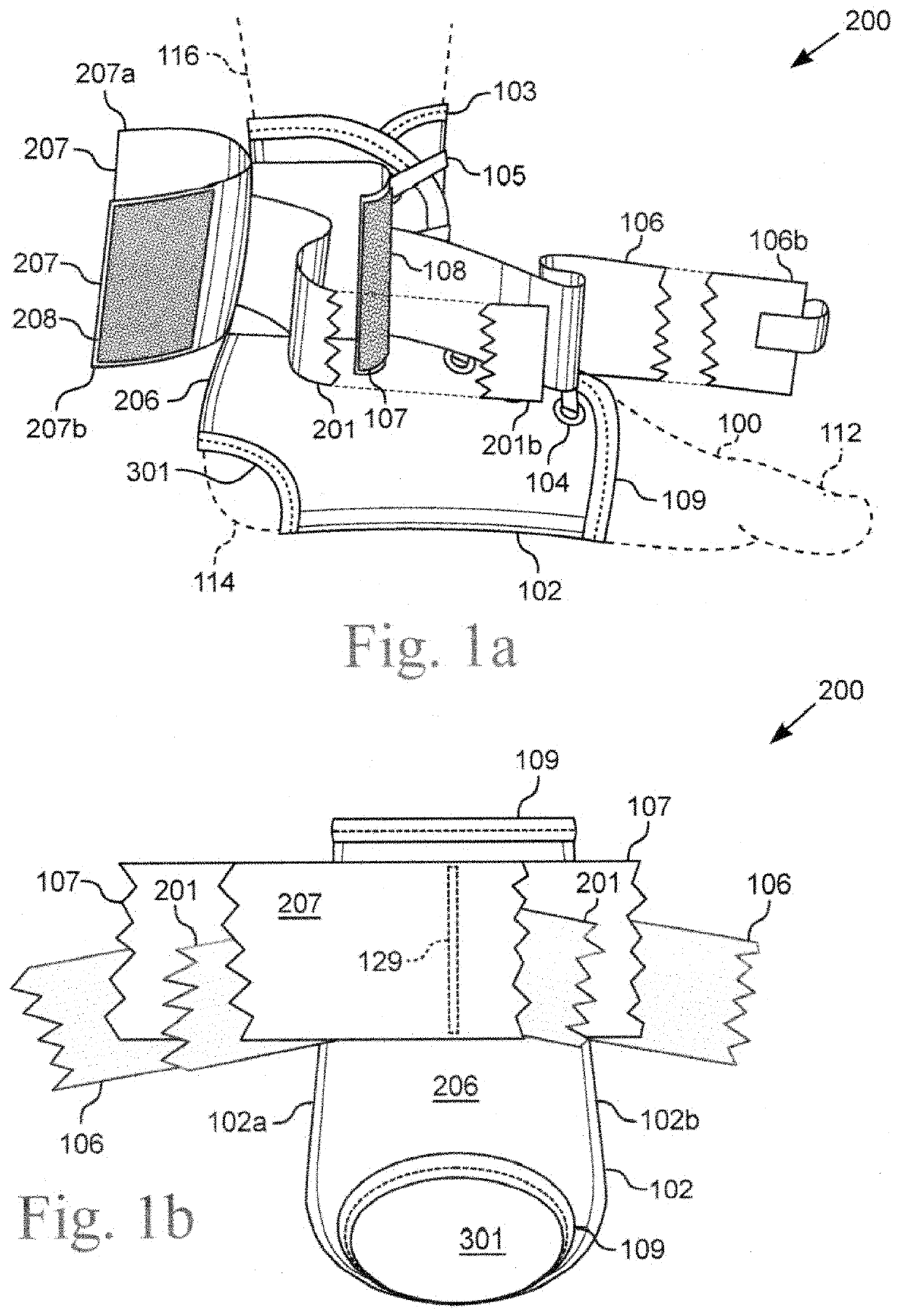
[0023]The following detailed description may recite various descriptive terms such as horizontal, vertical, top, bottom, upward, downward, left, right, etc., when referring to the figures, but the present general inventive concept is not limited to any such terms or physical orientations. Such terms are used for convenience of description only, and could be reversed, modified, or interchanged without departing from the broader scope and spirit of the present general inventive concept.

[0024]FIG. 1a illustrates a top view of one embodiment of the ankle brace 200. FIG. 1b illustrates a partial rear view of the ankle brace 200 shown in FIG. 1a. The ankle brace 200 includes a holding pocket 102, a first support strap 106, a first support cuff 107, a second support strap 201, and a second support cuff 207. The various straps 106, 201 and cuffs 107, 207 include various connectors, such as hook and loop closure material, that are shown in detail in various other figures.

[0025]The holding po...


PUM


Abstract

The present general inventive concept, in various embodiments, includes a brace for protective or therapeutic restraint of the ankle and / or foot. In some embodiments, the brace comprises a holding pocket of flexible material for stabilizing the ankle or foot, a means for releasably and adjustably attaching the holding pocket around the foot and ankle, a first support strap including a means for releasably and adjustably binding the first support strap to itself, a first support cuff including a means for releasably and adjustably tightening the first support cuff upon itself, a second support strap including a means for releasably and adjustably binding the second support strap to itself, and a second support cuff including a means for releasably and adjustably tightening the second support cuff upon itself.

Description

CROSS-REFERENCE TO RELATED APPLICATIONS[0001]Not Applicable.STATEMENT REGARDING FEDERALLY-SPONSORED RESEARCH OR DEVELOPMENT[0002]Not Applicable.BACKGROUND OF THE INVENTION[0003]The present general inventive concept relates generally to an ankle brace, and more specifically, a brace for protective or therapeutic restraint of the ankle or foot.BRIEF SUMMARY[0004]The present general inventive concept, in various embodiments, includes a brace for protective or therapeutic restraint of the ankle and / or foot. In some embodiments, the brace comprises a holding pocket for stabilizing the ankle or foot, the holding pocket being made from flexible material, the holding pocket also including a bottom having an interior surface and an exterior surface, a back having an interior surface and an exterior surface, a right side having an interior surface and an exterior surface, and a left side having an interior surface and an exterior surface, said bottom and said back being permanently affixed to...

Claims


Application Information

Patent Timeline
Patent Type & Authority Patents(United States)
IPC IPC(8): A61F5/01A61F13/06
CPCA61F5/0111A61F13/066A61F2005/0167A61F2005/0181
Inventor MCVEIGH, JASONBETCHER, RUSSELL
Owner MCVEIGH JASON
Why Eureka
Try Eureka