Blow pipe dart

a technology of blow pipe and dart, which is applied in the direction of white arms/cold weapons, ammunition projectiles, weapons components, etc., can solve the problem of reducing the risk of injury to such a person, and achieve the effect of reducing the speed of the blow pipe dart, reducing any pain, and being safer for us

Inactive Publication Date: 2017-01-10
HEPBURN RALPH ROBERTSON
View PDF7 Cites 0 Cited by
  • Summary
  • Abstract
  • Description
  • Claims
  • Application Information

AI Technical Summary

Benefits of technology

[0006]The nose may define a bore extending from the tip to the tapered portion. This would allow air expelled by a user into a blow pipe to pass through the nose of the dart, thereby reducing the speed of the dart to make it safer for use. Passage of air through the nose may also help the aerodynamic properties of the dart. Furthermore, by having an aperture at the tip (that is, by having a bore through the nose), the nose will deform easily on impact, thereby reducing any pain experienced by someone who is hit by the dart.
[0007]The body may be molded from soft rubber. This may also reduce any pain experienced by someone who is hit by the dart, and may lower the risk of injury to such a person.
[0008]The dart may further comprise a circular boss protruding from the circular body portion. This provides reduced contact between the dart and an inner wall of a blow pipe.

Problems solved by technology

This may also reduce any pain experienced by someone who is hit by the dart, and may lower the risk of injury to such a person.

Method used


Image

  • Blow pipe dart
  • Blow pipe dart
  • Blow pipe dart

Examples


Embodiment Construction

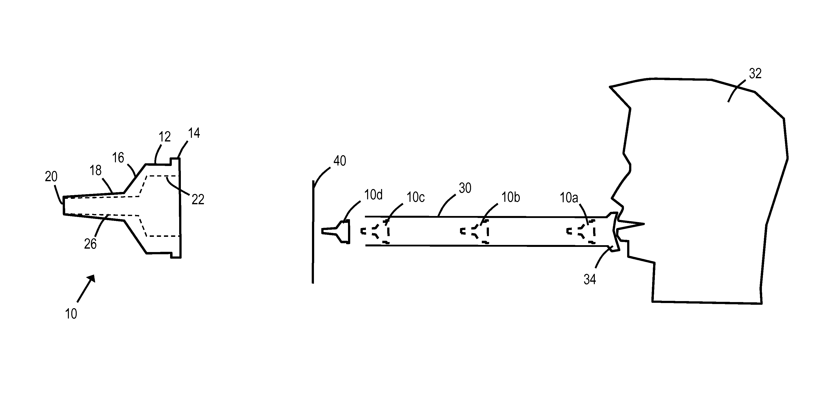
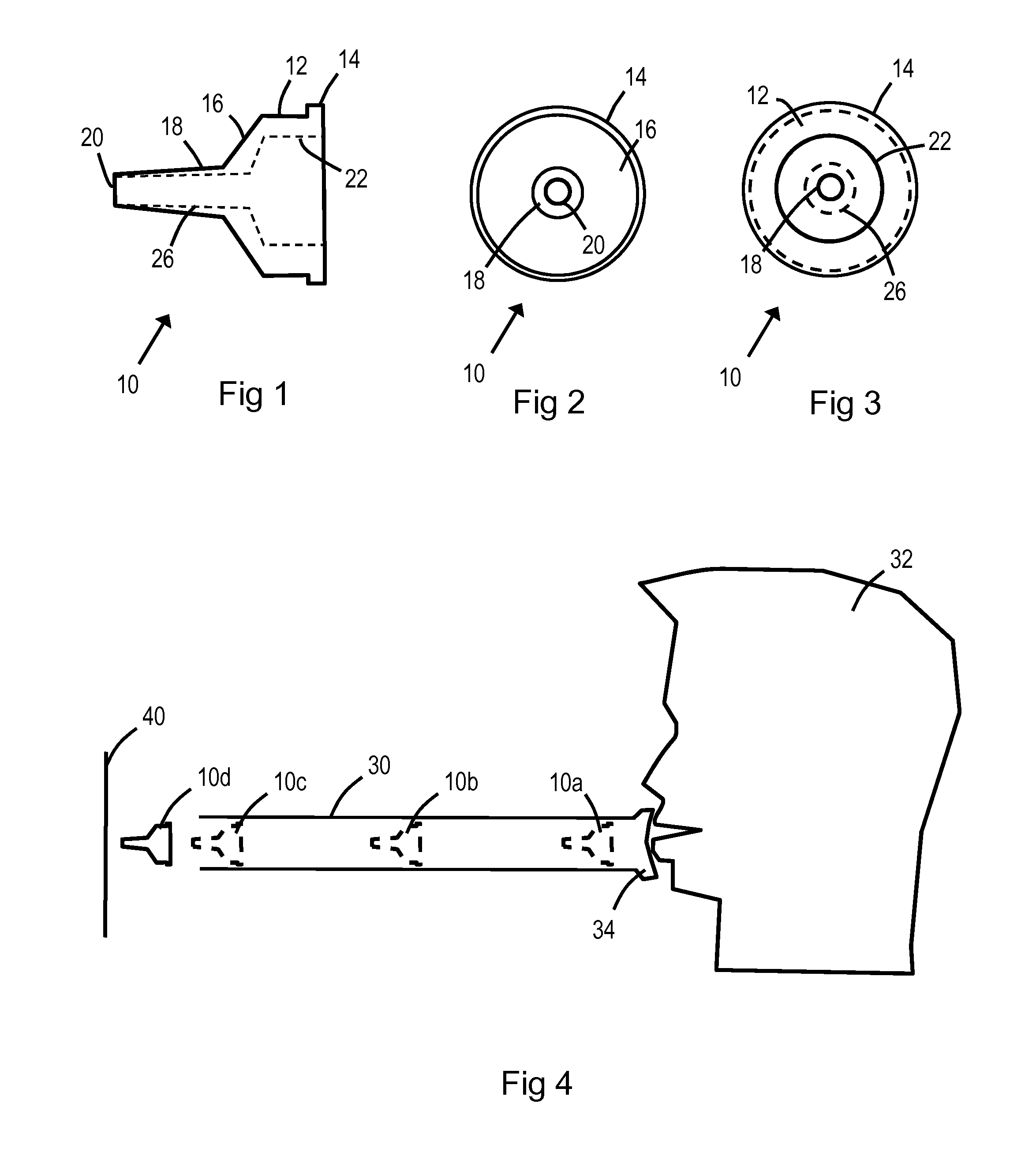
[0027]Reference will first be made to FIGS. 1 to 3, which illustrate a blow pipe dart 10 according to one embodiment of the present invention.

[0028]The dart 10 is injection molded from a single piece of elastomeric material (in this embodiment soft rubber) and comprises a generally circular body portion 12. In this embodiment, the body portion is approximately 19 mm in diameter. Extending outwardly from this circular body portion 12 by a small amount (approximately 0.5 mm in this embodiment) is a boss or rim 14. The boss 14 creates a small contact area for the dart 10 when located within a blow pipe (not shown in FIGS. 1 to 3).

[0029]A first tapered portion 16 extends from the body portion 12 to a nose 18. The first tapered portion 16 is approximately 4 mm long, and tapers from a diameter of approximately 19 mm to a diameter of approximately 7 mm.

[0030]In this embodiment, the nose 18 is also slightly tapered, from approximately 7 mm at the first tapered portion end to approximately 5...


PUM


Abstract

An elastomeric blow pipe dart (10) including: a generally circular body portion (12); a tapered portion (16) extending from the generally circular body portion (12); and a nose (18) having a smaller diameter than the tapered portion (16) and extending from the tapered portion (16) to a tip (20). The blow pipe dart (10) may comprise a soft rubber, and the nose (18) may define an end bore (26) so that air passes through the nose (18) when the dart (10) is launched.

Description

FIELD OF THE INVENTION[0001]The present invention relates to a blow pipe dart. In particular, although not exclusively, for use as a children's toy for target practice, games, and the like.BACKGROUND OF THE INVENTION[0002]Blow pipes are well known, but use of a blow pipe as a children's toy is hampered by the risk of injuring a person hit by a dart from such a blow pipe.[0003]It would be advantageous to obviate or mitigate this disadvantage.SUMMARY OF THE INVENTION[0004]According to a first aspect of the invention there is provided an elastomeric blow pipe dart comprising: a generally circular body portion, a tapered portion extending from the generally circular body portion, and a nose having a smaller diameter than the tapered portion and extending from the first tapered portion to a tip.[0005]The nose may taper from the tapered portion to the tip.[0006]The nose may define a bore extending from the tip to the tapered portion. This would allow air expelled by a user into a blow pip...

Claims


Application Information

Patent Timeline
Patent Type & Authority Patents(United States)
IPC IPC(8): F41F1/00F42B6/00F41B1/00
CPCF42B6/003F41B1/00
Inventor HEPBURN, RALPH ROBERTSON
Owner HEPBURN RALPH ROBERTSON
Why Eureka
Try Eureka