Contactor and handler
a technology of contactor and handler, which is applied in the direction of electronic circuit testing, measurement devices, instruments, etc., can solve the problems of difficulty in effectively increasing or achieve the effect of effectively increasing and decreasing the temperature of electronic components, preventing the effect of external air
- Summary
- Abstract
- Description
- Claims
- Application Information
AI Technical Summary
Benefits of technology
Problems solved by technology
Method used
Image

Examples
first embodiment
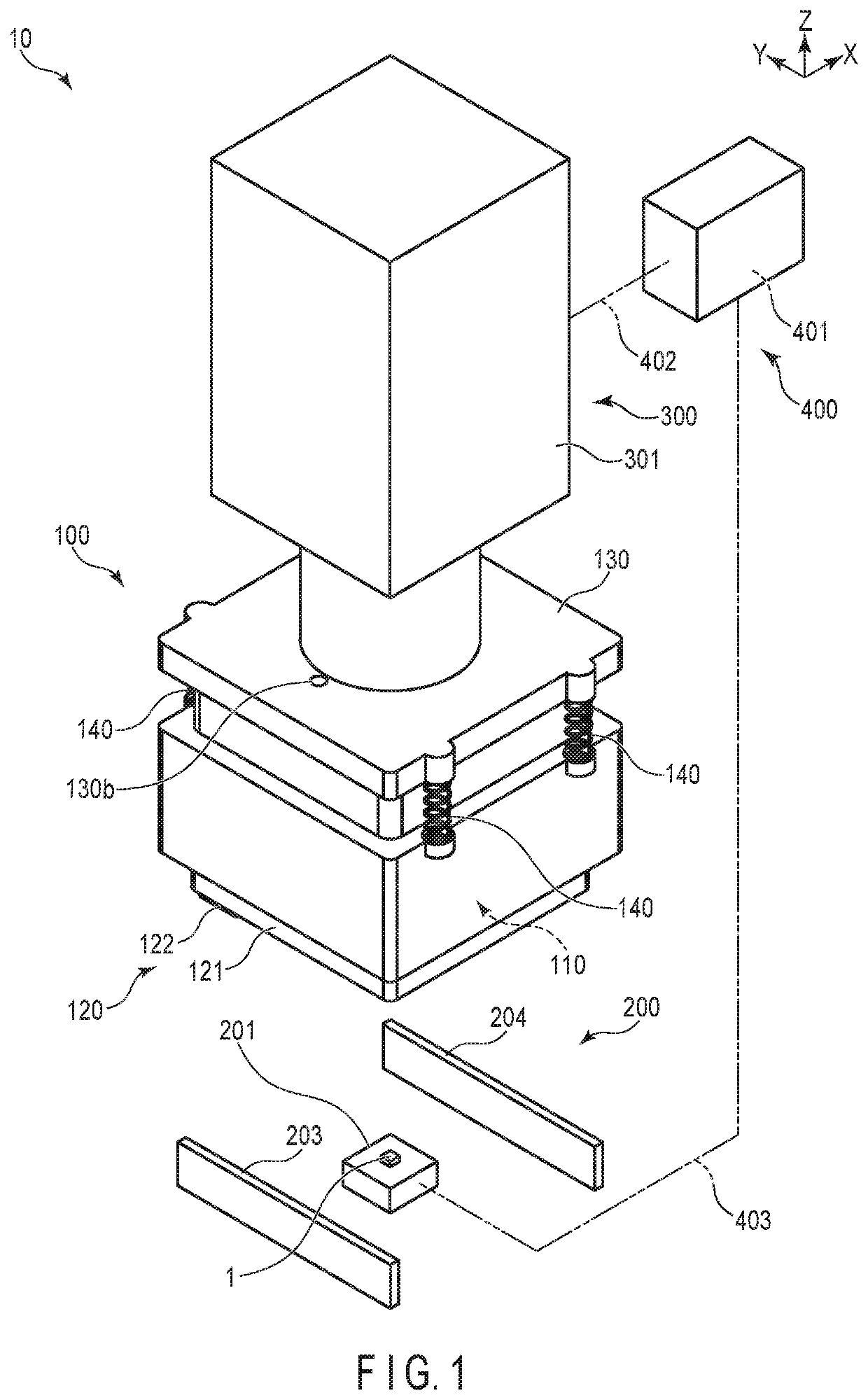
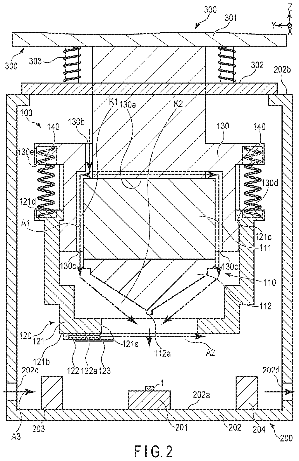
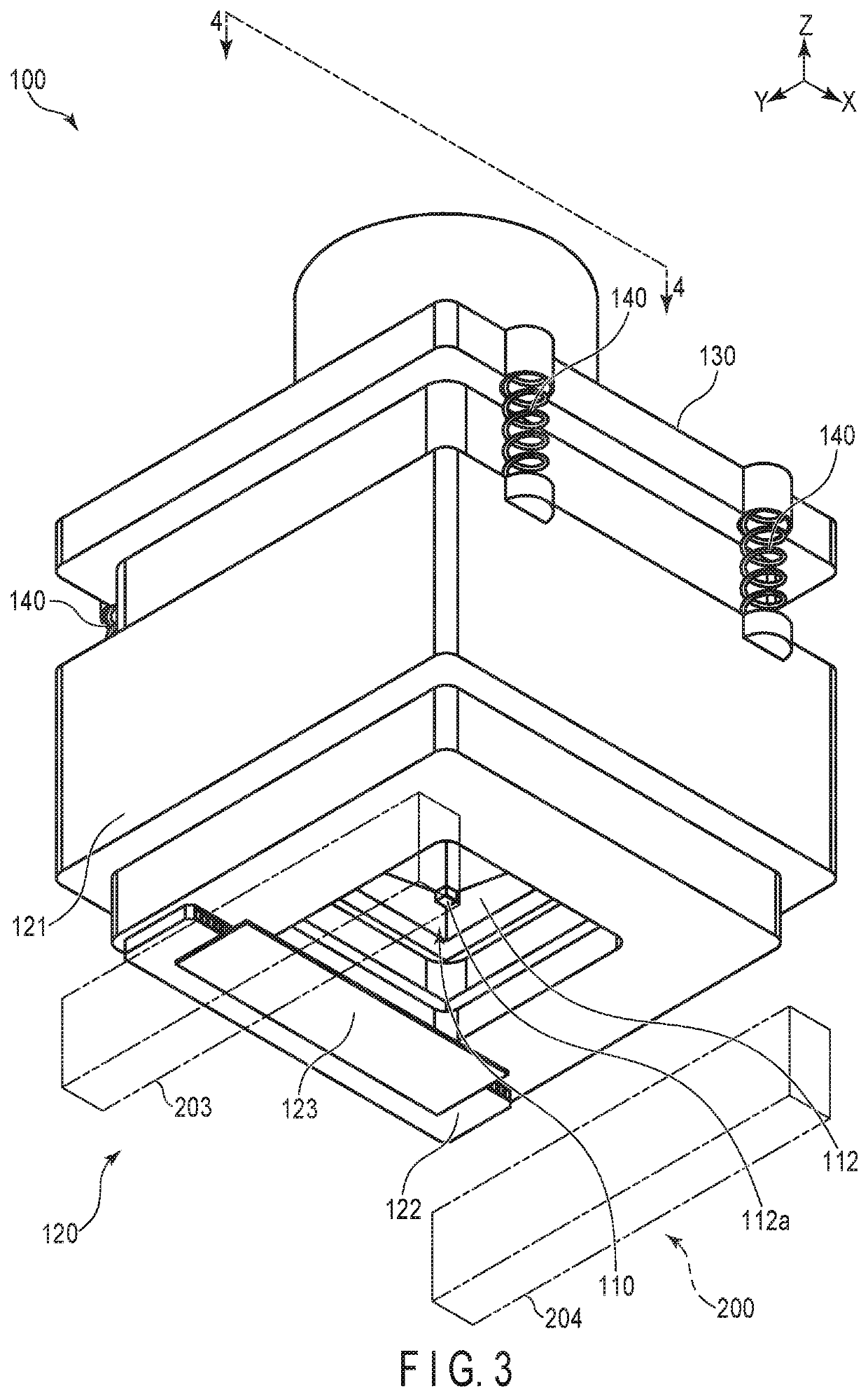
[0025]Hereinafter, this specification shows an example of an IC handler (handler) 10 including a contactor 100 as the first embodiment of the present invention. During the replacement of an IC chip 1 in an inspection device 200, the IC handler 10 of the first embodiment shields a temperature adjustment mechanism 110 provided in the contactor 100 against external air by the dry air A2 supplied from an air curtain 122 while supplying dry air A1 to the inside of a cover 121.
[0026]The structure of the IC handler 10 of the first embodiment is explained with reference to FIG. 1 to FIG. 6. FIG. 1 is a general perspective view showing the inside of the IC handler 10 according to the first embodiment. In FIG. 1, a part of the inspection device 200 and a driving device 300 is omitted. FIG. 2 is a general cross-sectional view of the IC handler 10 of FIG. 1. FIG. 3 is a general perspective view showing a part of the contactor 100 and inspection device 200 of FIG. 1. FIG. 4 is a general cross-se...
second embodiment
[0059]Hereinafter, this specification shows an example of a contactor 500 included in an IC handler as the second embodiment of the present invention with reference to FIG. 7 to FIG. 10. Unless otherwise specified, the present embodiment has the same structure as the first embodiment. During the replacement of an IC chip 1 in an inspection device 200, the IC handler of the second embodiment shields a temperature adjustment mechanism 110 provided in the contactor 100 against external air by an iris diaphragm 524 provided in a shielding mechanism 520, etc., while supplying dry air A1 to the inside of a cover 121.
[0060]The structure of the contactor 500 of the second embodiment is explained with reference to FIG. 7 to FIG. 10. FIG. 7 is a general perspective view showing a part of the contactor 500 and the inspection device 200 according to the second embodiment. FIG. 8 is a general cross-sectional view of the contactor 500 and the inspection device 200 along the 8-8 line of FIG. 7. FI...
third embodiment
[0067]Hereinafter, this specification shows an example of a contactor 600 included in an IC handler as the third embodiment of the present invention with reference to FIG. 11 to FIG. 14. Unless otherwise specified, the present embodiment has the same structure as the first embodiment. During the replacement of an IC chip 1 in an inspection device 200, the IC handler of the third embodiment shields a temperature adjustment mechanism 110 provided in the contactor 100 against external air by a bellows 621N and an iris diagram 524 provided in an shielding mechanism 620, etc., while supplying dry air A1 to the inside of a cover 621.
[0068]The structure of the contactor 600 of the third embodiment is explained with reference to FIG. 11 to FIG. 14. FIG. 11 is a general perspective view showing a part of the contactor 600 and the inspection device 200 according to the third embodiment. FIG. 12 is a general cross-sectional view of the contactor 600 and the inspection device 200 along the 12-1...
PUM
 Abstract
Description
Claims
Application Information
 - R&D Engineer
- R&D Manager
- IP Professional
- Industry Leading Data Capabilities
- Powerful AI technology
- Patent DNA Extraction
Browse by: Latest US Patents, China's latest patents, Technical Efficacy Thesaurus, Application Domain, Technology Topic.
© 2024 PatSnap. All rights reserved.Legal|Privacy policy|Modern Slavery Act Transparency Statement|Sitemap