System and method for biometric image capturing

a biometric and image technology, applied in the field of biometric image capture, can solve the problems of affecting the refraction index at the receiving surface, affecting the refraction index of the receiving surface, and affecting the reading of the prints, so as to reduce or eliminate the moisture and/or fluid, increase or decrease the temperature of the thermal elements, and increase the temperature of the platen

Inactive Publication Date: 2005-08-25
CROSS MATCH TECH
View PDF14 Cites 2 Cited by
  • Summary
  • Abstract
  • Description
  • Claims
  • Application Information

AI Technical Summary

Benefits of technology

[0012] On the other hand, heating the platen reduces or eliminates moisture and / or fluids around the area of the platen, where the biometric object is placed. Such reduction or elimination of excess moisture surrounding the biometric object on the platen prevents a halo effect from appearing in the detected print image.
[0013] In embodiments of the invention, a controller controls each thermal element to cool or heat the platen. In one embodiment, a controller supplies current to the thermal assembly in order to increase or decrease the temperature of the thermal elements. A temperature sensor, attached to the controller detects temperature of the platen. If the temperature of the platen is above a certain threshold level, the temperature sensor sends a signal to the controller to supply current to the thermal assembly in order to increase the temperature of the platen. Increasing temperature of the platen will reduce or eliminate moisture and a resulting halo effect. If the temperature of the platen is below a certain threshold level, the temperature sensor sends a signal to the controller to supply current to the thermal assembly in order to decrease the temperature of the platen.
[0014] In embodiments of the invention, the thermal elements, such as Peltier elements, are attached to the image capturing prism at locations where they do not affect the image illumination or fingerprint imaging. For example, in some embodiments, the thermal elements are located at the ends of the prism platen.
[0015] According to another feature of the present invention, the controller can be operated in a manual or automatic mode. In a manual mode, a user sets the controller to either a “cooling” or “heating” setting. The controller then controls the thermal assembly to cool or heat the platen accordingly. In an automatic mode, the controller automatically determines whether to cool or heat the platen based on detected ambient conditions (such as the ambient temperature and / or ambient humidity).
[0016] Further embodiments, features, and advantages of the present invention, as well as the structure and operation of the various embodiments of the present invention are described in detail below with reference to the accompanying drawings.

Problems solved by technology

This technique can be very messy due to the application of ink, and may often result in a set of prints that are difficult to read.
Excessive moisture and / or fluids on a finger, however, can be undesirable.
Excessive moisture and / or fluids may alter the refraction index at the receiving surface and interrupt the TIR of the prism in undesirable places on the receiving surface.
This can degrade image quality.
Excessive heat or cold at or near the platen surface can also degrade image quality.

Method used


Image

  • System and method for biometric image capturing
  • System and method for biometric image capturing
  • System and method for biometric image capturing

Examples


Embodiment Construction

Table of Contents

[0024] 1. Introduction.

[0025] 2. Terminology.

[0026] 3. Temperature Controlled Biometric Scanner.

[0027] 4. Temperature Based Controller.

[0028] (A) Cooling.

[0029] (B) Heating.

[0030] (C) Automatic Control.

[0031] 5. Thermal Coupling.

[0032] 6. Method for Changing Temperature of the Platen.

[0033] 7. Conclusion.

1. Introduction.

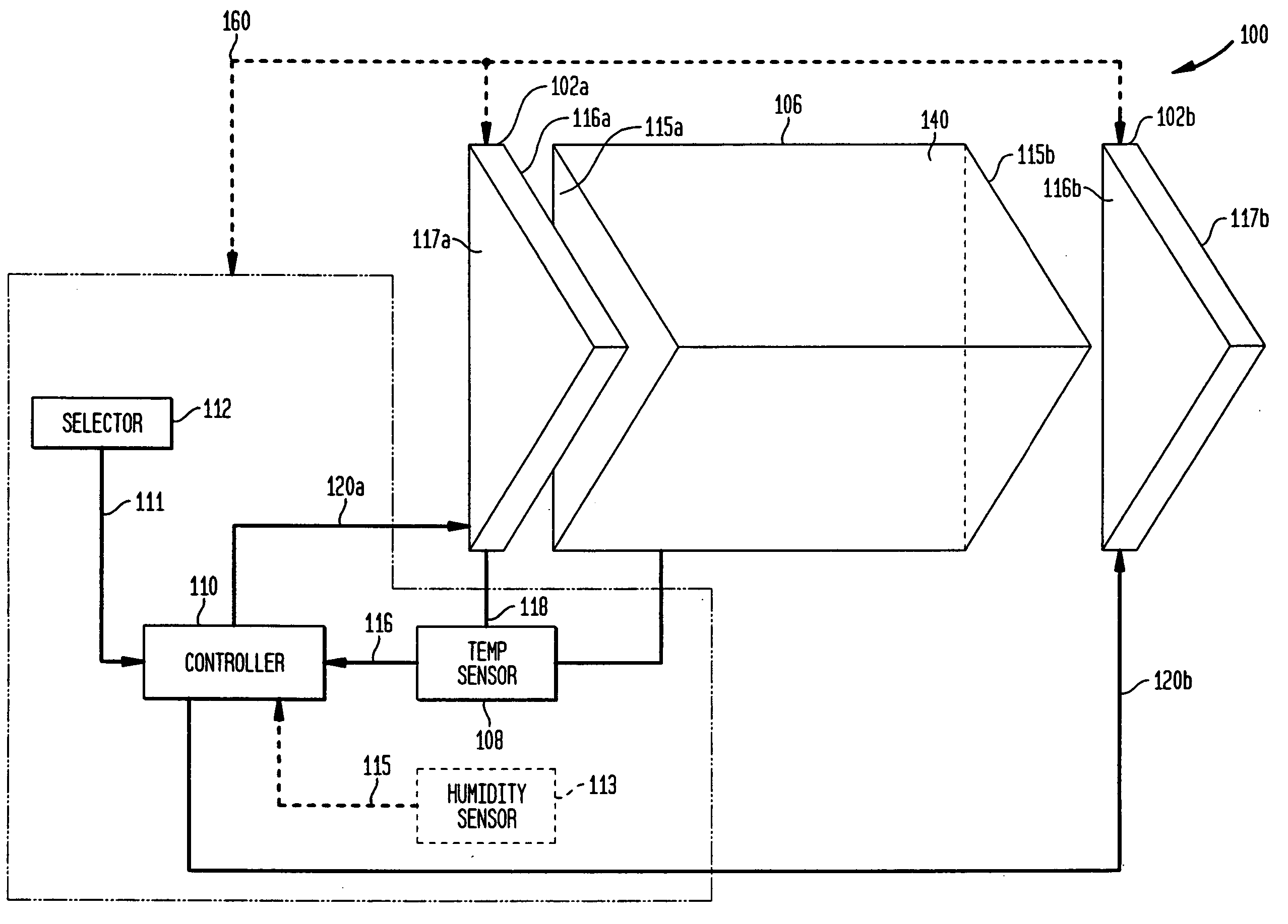
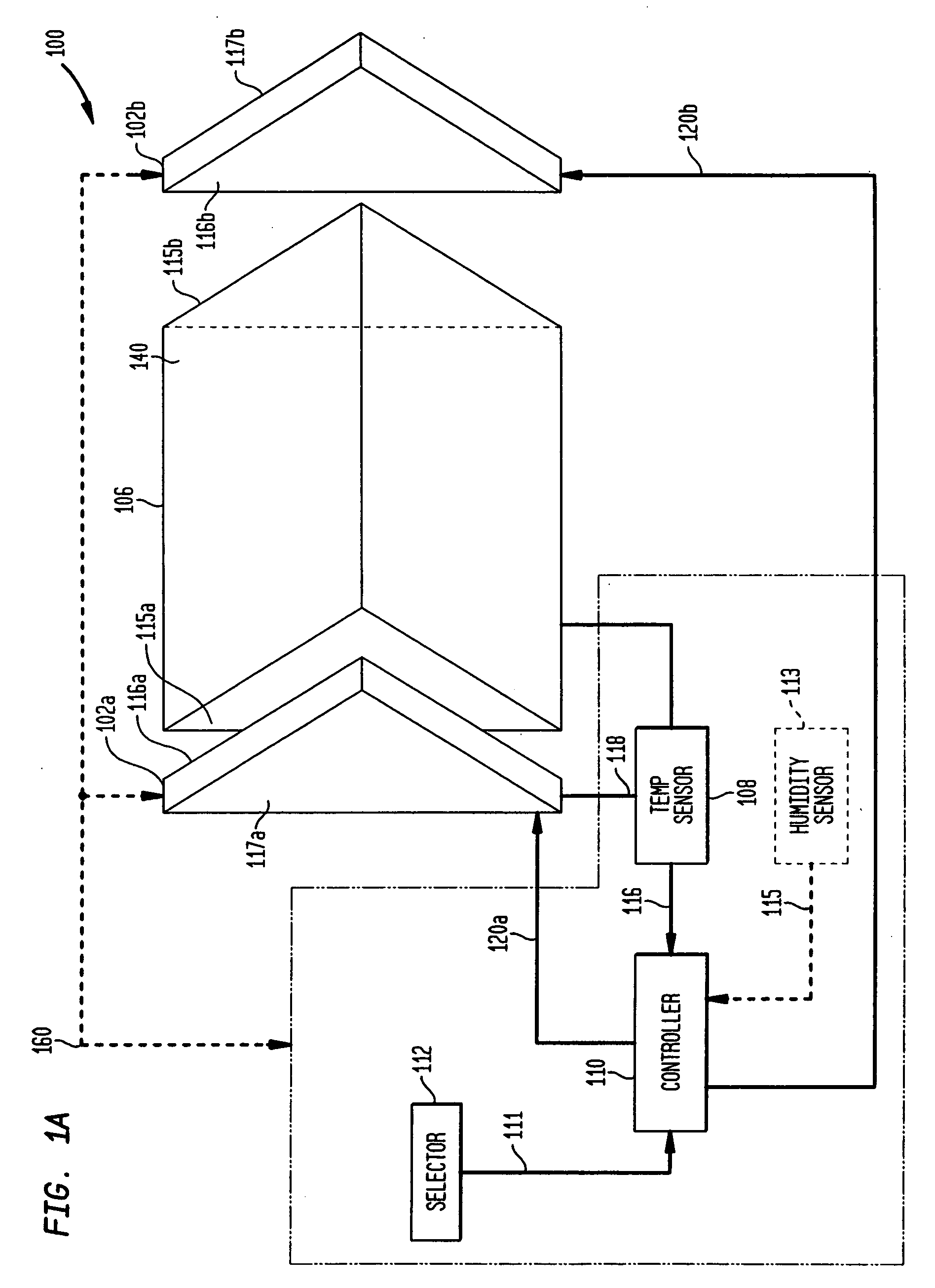
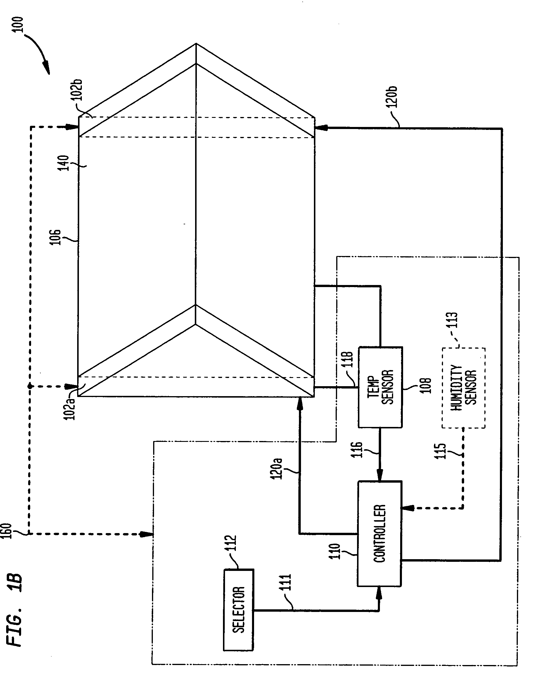
[0034] The present invention relates to systems and methods for capturing a biometric image using a live print scanning device. More specifically, the present invention relates to a live print scanner comprising an optical device coupled to a thermal assembly. The thermal assembly further comprises a controller. The controller is capable of either manually or automatically controlling temperature of the live print scanner's biometric object receiving surface or platen. In an embodiment, the controller can be used to adjust thermal states of the platen based on a variety of ambient conditions.

[0035] Although the invention will be describ...


PUM


Abstract

Devices and methods for applying heat to a platen of a biometric image capturing device are described that remove and prevent the formation of excess moisture on the platen. These devices and methods prevent undesirable interruptions of total internal reflection of a prism that result in biometric images having a halo effect. In embodiments of the invention, heater assemblies, such as electrically conductive transparent material or resistive heating elements, can be used to heat an area where a biometric object is placed to remove and prevent the formation of excess moisture on the platen. Cooling assemblies, such as electrically conductive transparent material or Peltier elements, can be used to decrease temperature of an area where a biometric object is placed to prevent overheating of the platen.

Description

CROSS-REFERENCE TO RELATED APPLICATIONS [0001] This application is a continuation of U.S. application Ser. No. 10 / 235,6656, filed Sep. 6, 2002, titled “System and Method for Biometric Image Capturing,” which is a Continuation-in-Part of U.S. application Ser. No. 10 / 047,983, filed Jan. 17, 2002 (now U.S. Pat. No. 6,809,303, issued Oct. 26, 2004), titled “Platen Heaters for Biometric Image Capturing Devices,” each of which is incorporated herein by reference in its entirety.FIELD OF THE INVENTION [0002] The present invention is directed to the field of biometric image capturing. BACKGROUND OF THE INVENTION [0003] Biometrics is the science of biological characteristic analysis. Biometric imaging captures a measurable characteristic of a human being for identification of the particular individual (for example, a fingerprint). See, for example, Gary Roethenbaugh, Biometrics Explained, International Computer Security Association, Inc., pp. 1-34 (1998), which is incorporated by reference h...

Claims


Application Information

Patent Timeline
Patent Type & Authority Applications(United States)
IPC IPC(8): G06V40/13H05B3/24
CPCH05B3/24G06K9/00013G06V40/13
Inventor CARVER, JOHN F.MCCLURG, GEORGE W.ARNOLD, JOSEPH F.
Owner CROSS MATCH TECH
Why Eureka
Try Eureka