Compensator for multiple surface imaging

Active Publication Date: 2009-11-05
ILLUMINA INC
View PDF3 Cites 173 Cited by
  • Summary
  • Abstract
  • Description
  • Claims
  • Application Information

AI Technical Summary

Benefits of technology

[0006]Accordingly, the invention provides a method for imaging a biological sample. The method includes detecting radiation emitted from a first emissive component of a biological sample disposed on a first surface of a flow cell using a detector. The flow cell is mounted on an imaging station. The method also includes inserting corrective optics between the detector and the flow cell. The method further includes detecting radiation emitted from a second emissive

Problems solved by technology

Although microarrays allow separate biological components to be presented for bulk processing and individual detection, the number of components that can be detected in

Method used


Image

  • Compensator for multiple surface imaging
  • Compensator for multiple surface imaging
  • Compensator for multiple surface imaging

Examples


Embodiment Construction

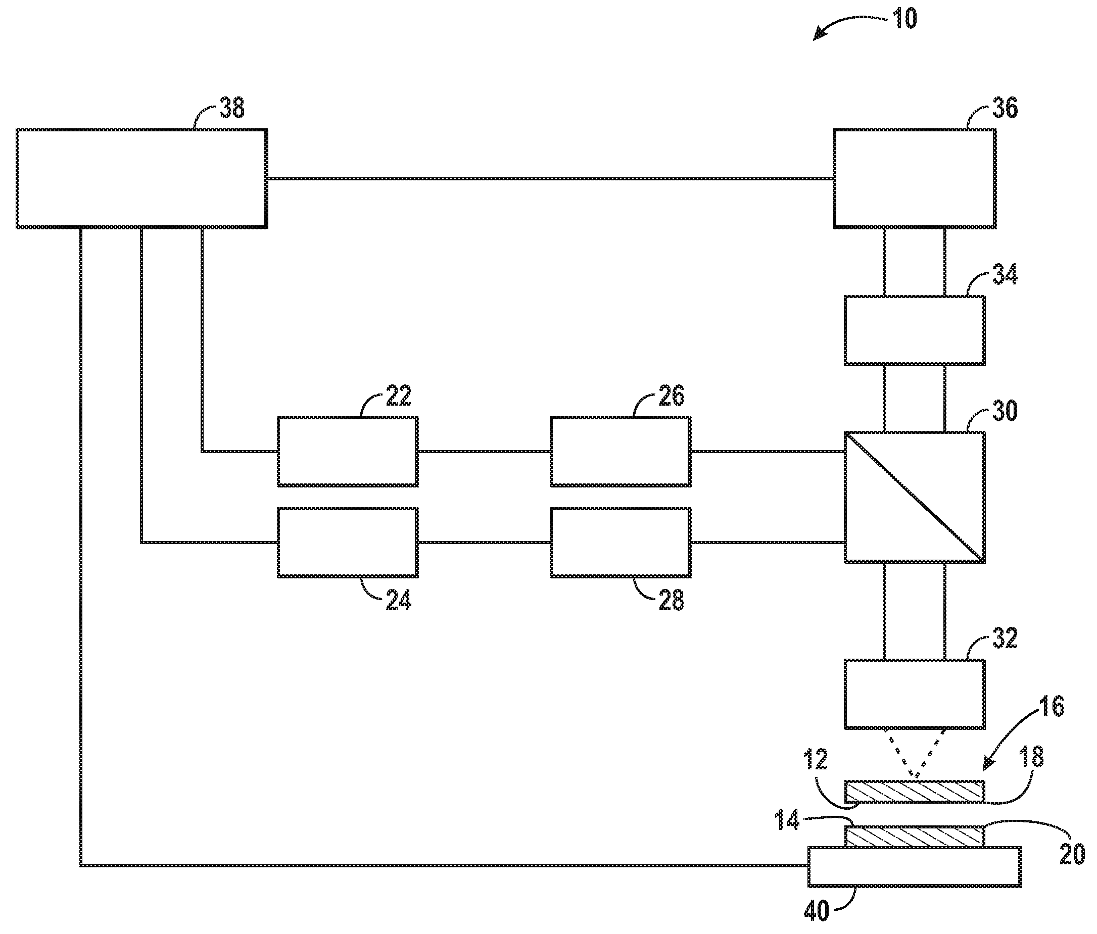
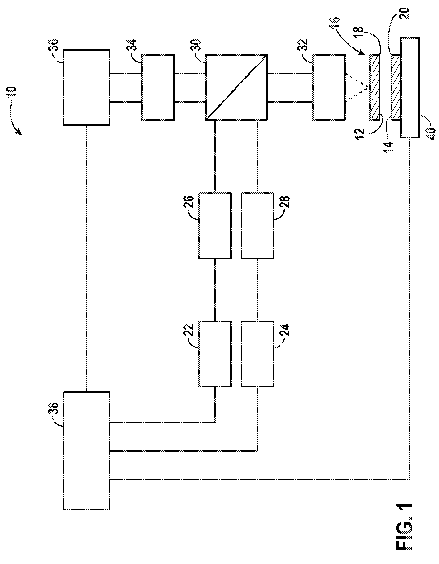
[0037]Turning now to the drawings, and referring first to FIG. 1, a biological sample imaging system 10 is illustrated diagrammatically. The biological sample imaging system 10 is capable of imaging multiple biological components 12, 14 within a support structure 16. For instance, in the illustrated embodiment, a first biological component 12 may be present on a first surface 18 of the support structure 16 while a second biological component 14 may be present on a second surface 20 of the support structure. The support structure 16 may, for instance, be a flow cell with an array of biological components 12, 14 on the interior surfaces 18, 20 which generally mutually face each other and through which reagents, flushes, and other fluids may be introduced, such as for binding nucleotides or other molecules to the sites of biological components 12, 14. The support structure 16 may be manufactured in conjunction with the present techniques or the support structure 16 may be purchased or ...


PUM

PropertyMeasurementUnit
Volumeaaaaaaaaaa
Wavelengthaaaaaaaaaa
Emissivityaaaaaaaaaa

Abstract

A system and method for imaging biological samples on multiple surfaces of a support structure are disclosed. The support structure may, for instance, be a flow cell through which a reagent fluid is allowed to flow and interact with the biological samples. Excitation radiation from at least one radiation source may be used to excite the biological samples on multiple surfaces. In this manner, fluorescent emission radiation may be generated from the biological samples and subsequently captured and detected by detection optics and at least one detector. The captured and detected fluorescent emission radiation may then be used to generate image data. This imaging of multiple surfaces may be accomplished either sequentially or simultaneously. In addition, the techniques of the present invention may be used with any type of imaging system. For instance, both epifluorescent and total internal reflection (TIR) methods may benefit from the techniques of the present invention. In addition, the biological samples imaged may be present on the surfaces of the support structure in a random special pattern and need not be at known locations in order for the imaging to be performed.

Description

CROSS REFERENCE TO RELATED APPLICATIONS[0001]This application claims priority of U.S. Provisional Patent Application No. 61 / 050,522, entitled “Multi-Surface Biological Sample Imaging System and Method,” filed May 5, 2008, which is herein incorporated in its entirety by reference, and of U.S. Provisional Patent Application No. 61 / 138,444, entitled “Compensator for Multiple Surface Imaging,” filed Dec. 17, 2008, which is herein incorporated in its entirety by reference.BACKGROUND[0002]The present invention relates generally to the field of imaging and evaluating analytical samples. More particularly, the invention relates to a technique for imaging and evaluating analytical samples on multiple surfaces of a support structure using a compensator.[0003]There are an increasing number of applications for imaging of analytical samples on a support structure. These support structures may include plates upon which biological samples are present. For instance, these plates may include deoxyri...

Claims


Application Information

Patent Timeline
IPC IPC(8): G01N21/64
CPCG01N21/05G01N21/6458G01N2021/6419G01N2021/6421C12Q1/6869G02B2207/113G01N2021/0346C12Q1/6874C12Q1/6825G02B21/0024
Inventor FENG, WENYIBRYANT, JASONBUERMANN, DALE
Owner ILLUMINA INC
Why Eureka
Try Eureka