Lace down insole systems

a technology of insoles and lace-ups, which is applied in the direction of insoles, fastenings, footwear, etc., can solve the problems of inconvenient user slipping their feet into and out of shoes without additional adjustments, wearers feeling uncomfortable,

Active Publication Date: 2022-06-28
BERRY JR JONATHAN LEE
View PDF9 Cites 0 Cited by
  • Summary
  • Abstract
  • Description
  • Claims
  • Application Information

AI Technical Summary

Benefits of technology

[0009]The present invention advantageously fills the aforementioned deficiencies by footwear shoelace accessories. The present invention is superior to other systems in that it effectively provides a shoe insole designed to hide the shoelaces underneath the insole.
[0010]The lace down insole system provides for a removable shoe insole with hook and loop fasteners on the bottom side of the insole as a method for retaining shoelaces underneath the insole. This allows an efficient way for allowing shoes to have the ability to slide on and off without the need for tying the shoelaces. The lace down insole system may be lifted towards the heel allowing the original shoelaces to hide underneath the insole. Upon pushing the insole back inside the shoe, the shoelaces will therefore be made stationary beneath the insole by means of the added hook and loop fasteners or another stationary material, thereby hiding the shoelaces and converting an ordinary shoe from needing to be tied, into a comfortable and secure slip on shoe.

Problems solved by technology

Tightening the lacing and tying off the ends secures the foot within the shoe, but sometimes makes the wearer feel uncomfortable.
Other lace-look accessories make it inconvenient for the user to slip their feet into and out of a shoe without additional adjustments being made for comfort.

Method used


Image

  • Lace down insole systems
  • Lace down insole systems
  • Lace down insole systems

Examples


Embodiment Construction

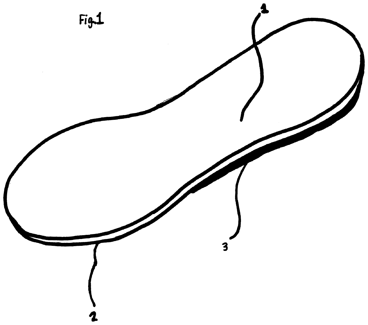
[0019]The present invention is directed to a lace down insole system. In one embodiment of the present invention, lace down insole systems may comprise a top side and bottom side with a plurality of hook and loop fasteners configured for the secure organization and retention of shoe laces.

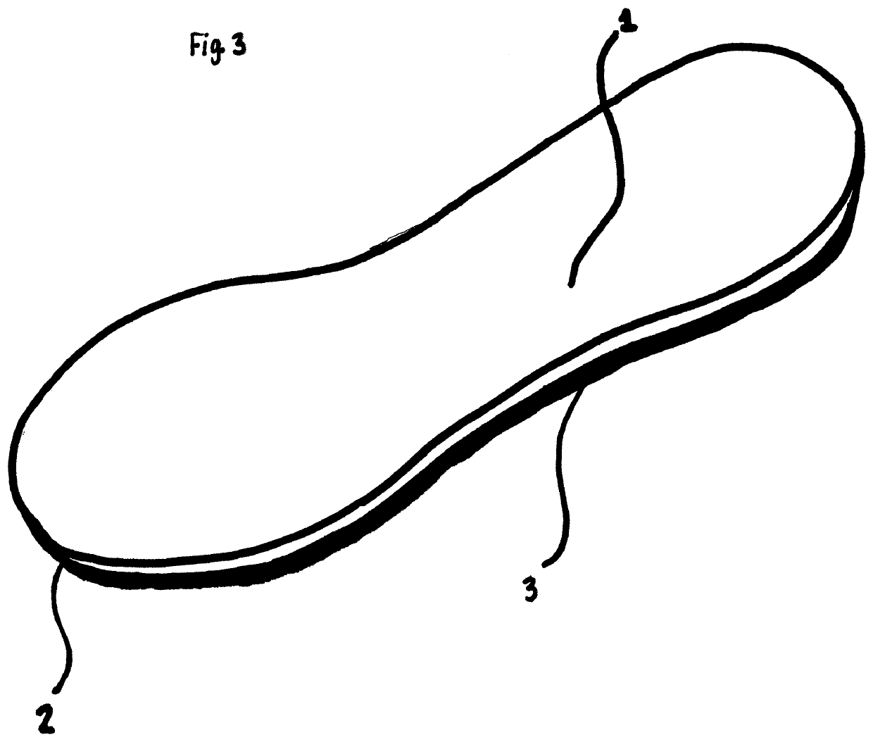
[0020]Referring now to the drawings, there is shown in FIG. 1 a lace down insole system including a top side (1) and bottom side (2). The back portion of the bottom side has a hook and loop slab (3). The hook and loop slab (3) may be constructed from hook and loop fasteners or another similar material fastener.

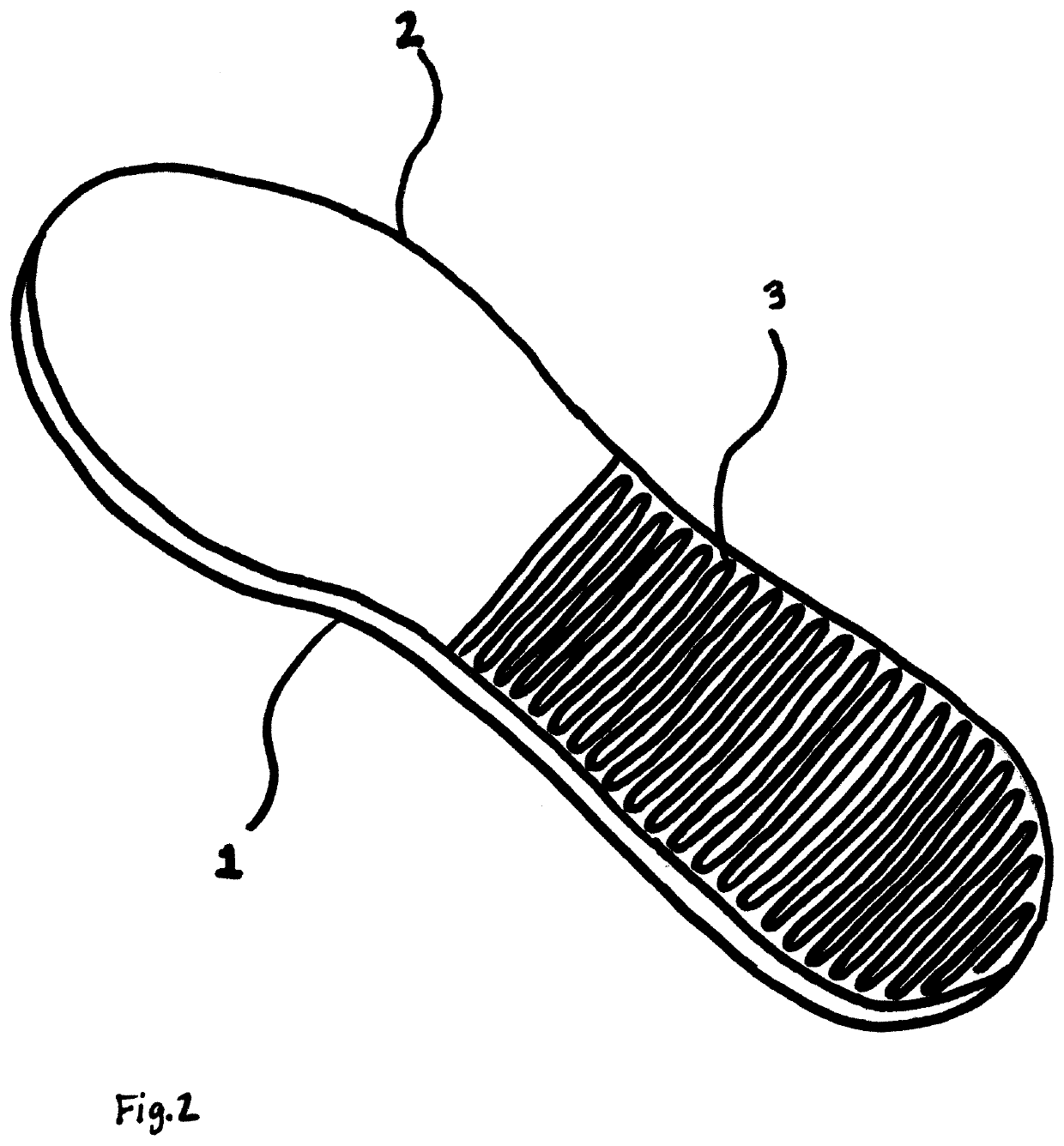
[0021]Referring now to FIG. 2 showing a bottom perspective view of a lace down insole system including a top side (1) and a bottom side (2) with a hook and loop slab (3) from the middle the insole to the heel of the insole. The bottom side (2) shows the hook and loop slab (3), with the “U”-shaped hook and loop ‘male’ side. The hook and loop slab (3) is a large portion of hook and loop type ma...


PUM


Abstract

The lace down insole system provides a removable shoe insole using hook and loop type fasteners as a method for retaining shoelaces beneath the insole. The lace down insole may comprise a top side and a bottom side with a plurality of “male” hook and loop type fasteners strategically placed on the bottom side of the insole, allowing the original shoelaces to be placed underneath the heel portion of the insole. This allows an efficient way for allowing shoes to have the ability to slide on and off without the need for tying the shoelaces.

Description

BACKGROUND OF THE INVENTION1. Field of the Invention[0001]The present invention relates generally to the field of footwear and more specifically relates to shoe lacing systems.2. Description of the Related Art[0002]Shoelaces, sometimes called shoestrings or bootlaces, are a system commonly used to secure shoes, boots, and other footwear. They typically consist of a pair of strings or cords, one for each shoe, finished off at both ends with stiff sections, known as aglets. Each shoelace typically passed through a series of holes, eyelets, loops or hooks on either side of the shoe. Loosening the lacing allows the shoe to open wide enough for the foot to be inserted or removed. Tightening the lacing and tying off the ends secures the foot within the shoe, but sometimes makes the wearer feel uncomfortable.[0003]Insoles are the interior bottom of a shoe, which sits directly beneath the foot under the footbed (also known as sock liner). The purpose of insole is to attach to the lasting ma...

Claims


Application Information

Patent Timeline
Patent Type & Authority Patents(United States)
IPC IPC(8): A43C7/00A43B17/00
CPCA43C7/00A43B17/006A43B17/00A43B11/00A43B1/0081
Inventor BERRY, JR., JONATHAN LEE
Owner BERRY JR JONATHAN LEE
Why Eureka
Try Eureka