
Valve device with cleaning wire

a valve device and cleaning wire technology, applied in the direction of valve operating means/releasing devices, functional valve types, mechanical devices, etc., can solve the problems of water hammer effect, which is characteristic of commercial toilets and urinals, and can be very destructive to the piping/plumbing system and disruptive to users

Active Publication Date: 2022-07-19
AS AMERICA
View PDF13 Cites 0 Cited by
  • Summary
  • Abstract
  • Description
  • Claims
  • Application Information

AI Technical Summary

Benefits of technology

The patent describes products and methods for reducing the size of flush valves and minimizing the water hammer effect in commercial flushometers. The invention achieves this by designing a pin that eliminates the bulky coil spring mechanism of current designs, allowing for downsizing of the flush valve. Additionally, the patent describes a flow head device that helps control the flush volume and minimize the force with which the main valve may close at the end of a flush cycle, reducing the impact on the piping / plumbing system and improving user experience.

Problems solved by technology

Additionally, the water hammer effect often characteristic of commercial toilets and urinals can be very destructive to the piping / plumbing system and disruptive to users.

Method used


Image

  • Valve device with cleaning wire
  • Valve device with cleaning wire
  • Valve device with cleaning wire

Examples


Embodiment Construction

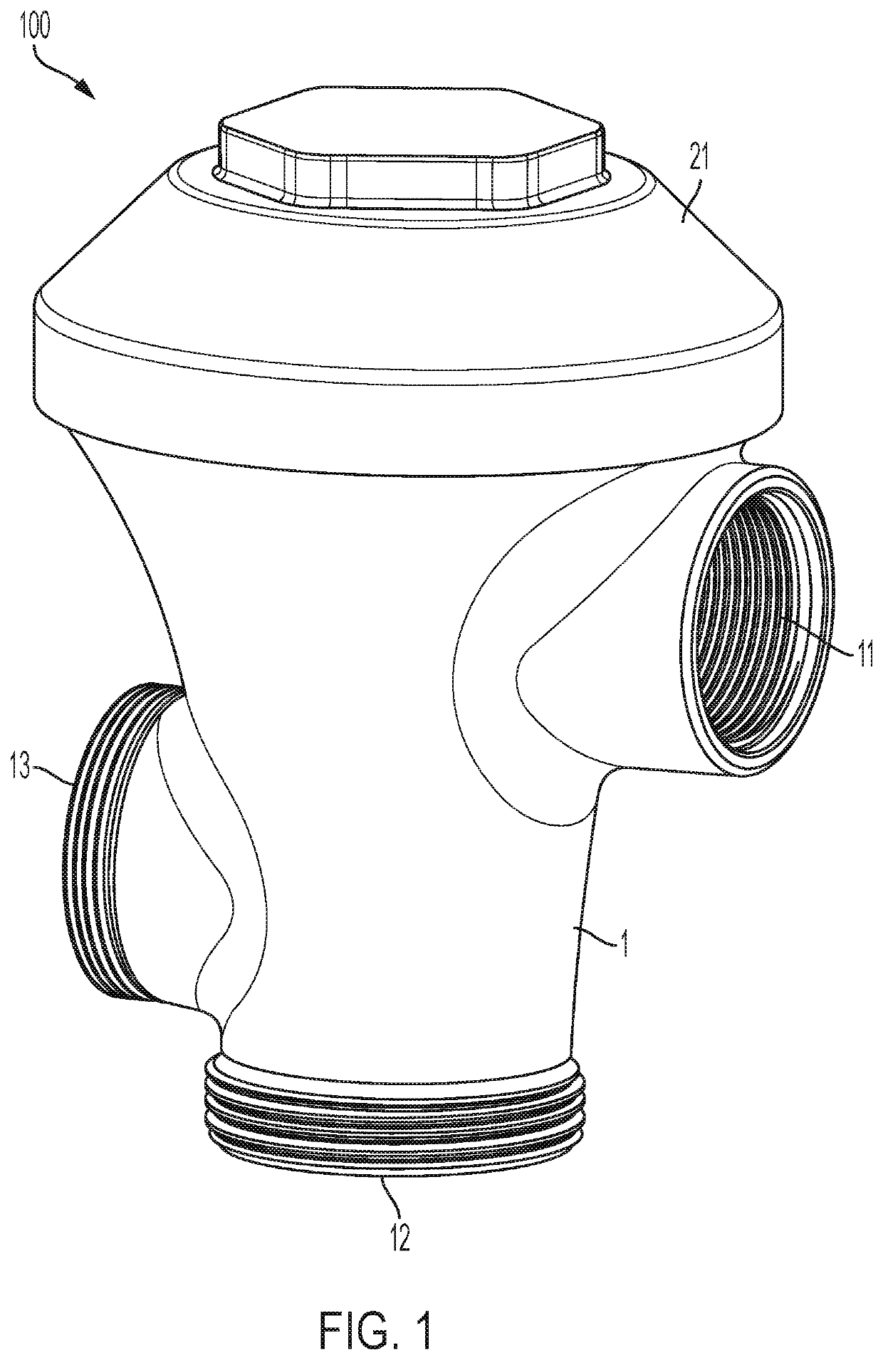
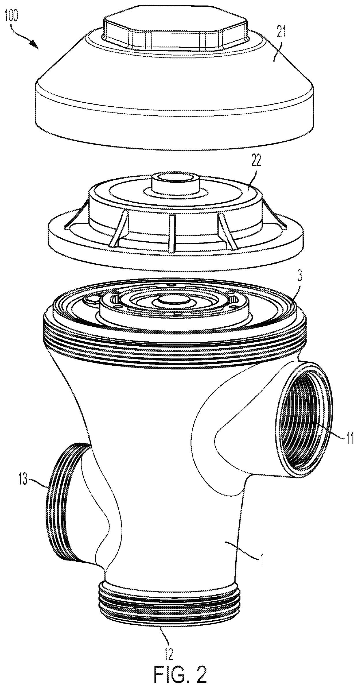
[0034]Described are improved flush valves and flow head devices for flush valves. In particular, described are improved flush valves that may be downsized without compromising any features and flow head devices that can minimize any water hammer effect in a flushometer.

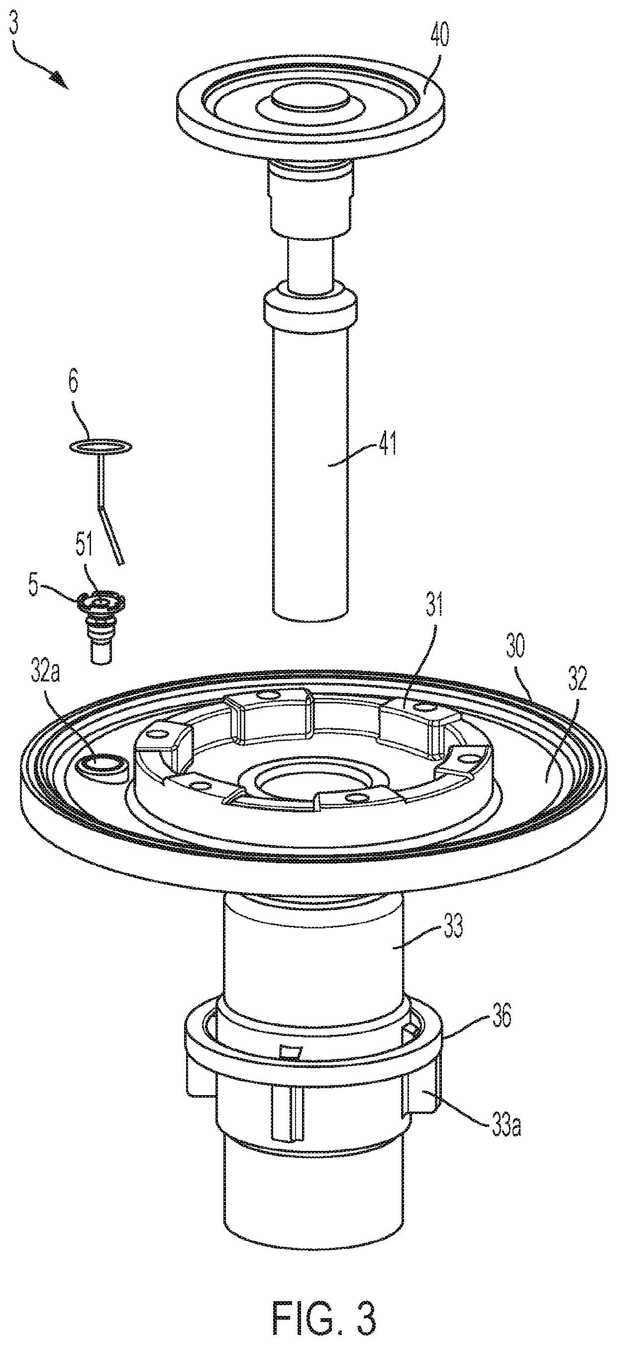
[0035]The inventors have developed a product that allows for a flush valve to be resized without compromising any features of the valve. For example, cleaning pins known in the art cannot simply be downsized proportionally with the flush valve itself while maintaining proper operability. Instead, most pins of conventional valve devices comprise a coil spring mechanism. However, this coil spring prevents the flush valve from being downsized. The inventors have developed a pin design that eliminates the bulky coil spring mechanism but can still move up and down and rotate to clean the hole in the main relief valve. Accordingly, pin designs according to embodiments herein allow for downsizing of a flush valve.

[0036]Addit...


PUM


Abstract

Provided are valve devices and flow heads for a valve device. A valve device can include a valve body (30) that opens and closes a valve hole (15a) to allow communication between a primary flow path (17a) and a secondary flow path (17b), a back pressure chamber (7) defined at the back side of the valve body, a small hole (51) that is provided in the valve body to allow the primary flow path of and the back pressure chamber to communicate with each other, and a pin (6) that has a straight portion inserted into the small hole to clean the small hole by relative motions of the small hole and the straight portion. A flow head (34) may be annular and include one or more notches along a perimeter and be configured to engage with an inner peripheral surface of an upper end portion of an inner barrel of the valve device.

Description

REFERENCE TO RELATED APPLICATIONS[0001]This application claims the benefit of U.S. Provisional Application No. 62 / 673,659, filed May 18, 2018, the entire contents of which are hereby incorporated by reference herein.FIELD OF THE INVENTION[0002]The present invention relates to valve devices. In particular, the present invention relates to flush valve devices.BACKGROUND OF THE INVENTION[0003]Unlike most residential buildings, commercial buildings typically have a large water supply line. Thus, modern commercial toilets and urinals often include a flushometer, instead of a water tank of most residential-type toilets. A flushometer requires a large water supply line to operate properly. A flushometer uses the water pressure from the large water supply line to provide a high-pressure flush.[0004]Flush valves typically include a diaphragm separating a pressure chamber (or back pressure chamber) from the main water supply. When a flush valve is in steady state (not cycling through a flush)...

Claims


Application Information

Patent Timeline
Patent Type & Authority Patents(United States)
IPC IPC(8): E03D3/06F16K21/12F16K31/385
CPCE03D3/06F16K21/12F16K31/3855
Inventor MARINOV, MARINPITSCH, WALTERSOBERANO, ERICSHIMIZU, KOJIWATARI, KOJIRO
Owner AS AMERICA
Learn More