Check patentability & draft patents in minutes with Patsnap Eureka AI!

Tube coupling assembly

a technology of coupling assembly and tube, which is applied in the direction of couplings, pipe joints, adjustable joints, etc., can solve the problems of easy installation, risk of leakage, and inability to fool human error in installation, so as to prevent separation

Active Publication Date: 2022-08-09
GENERAL ELECTRIC CO
View PDF37 Cites 0 Cited by
  • Summary
  • Abstract
  • Description
  • Claims
  • Application Information

AI Technical Summary

Problems solved by technology

Fluid couplings can get loose due to vibration or shocks causing risk of leakage while in operation.
It is easy to install but not foolproof for human error in installation.
If not installed properly it can cause foreign object damage, and risk of injury to the operator.
This complicates field maintenance of systems that include safety cable.

Method used


Image

  • Tube coupling assembly
  • Tube coupling assembly
  • Tube coupling assembly

Examples


Embodiment Construction

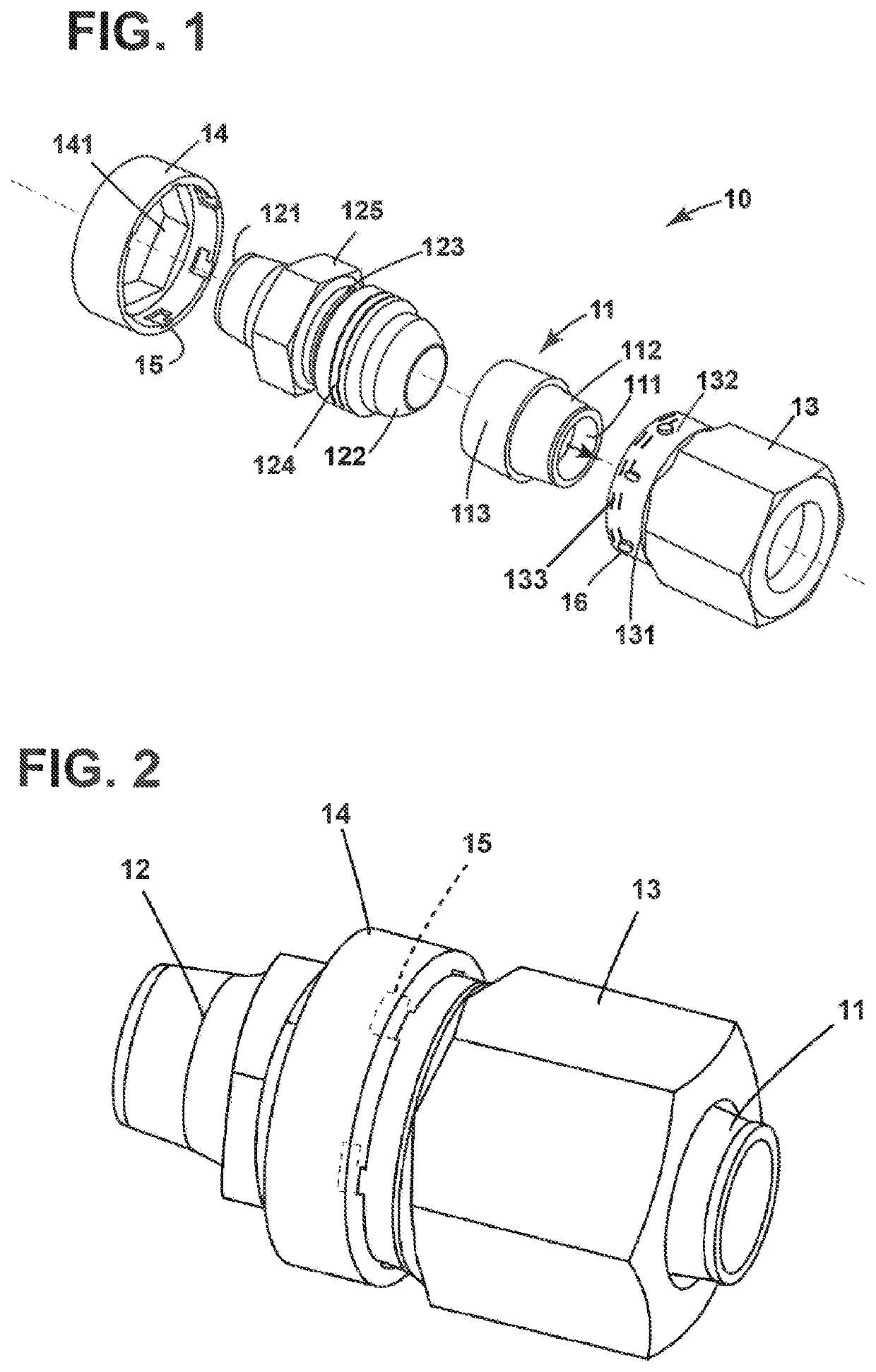
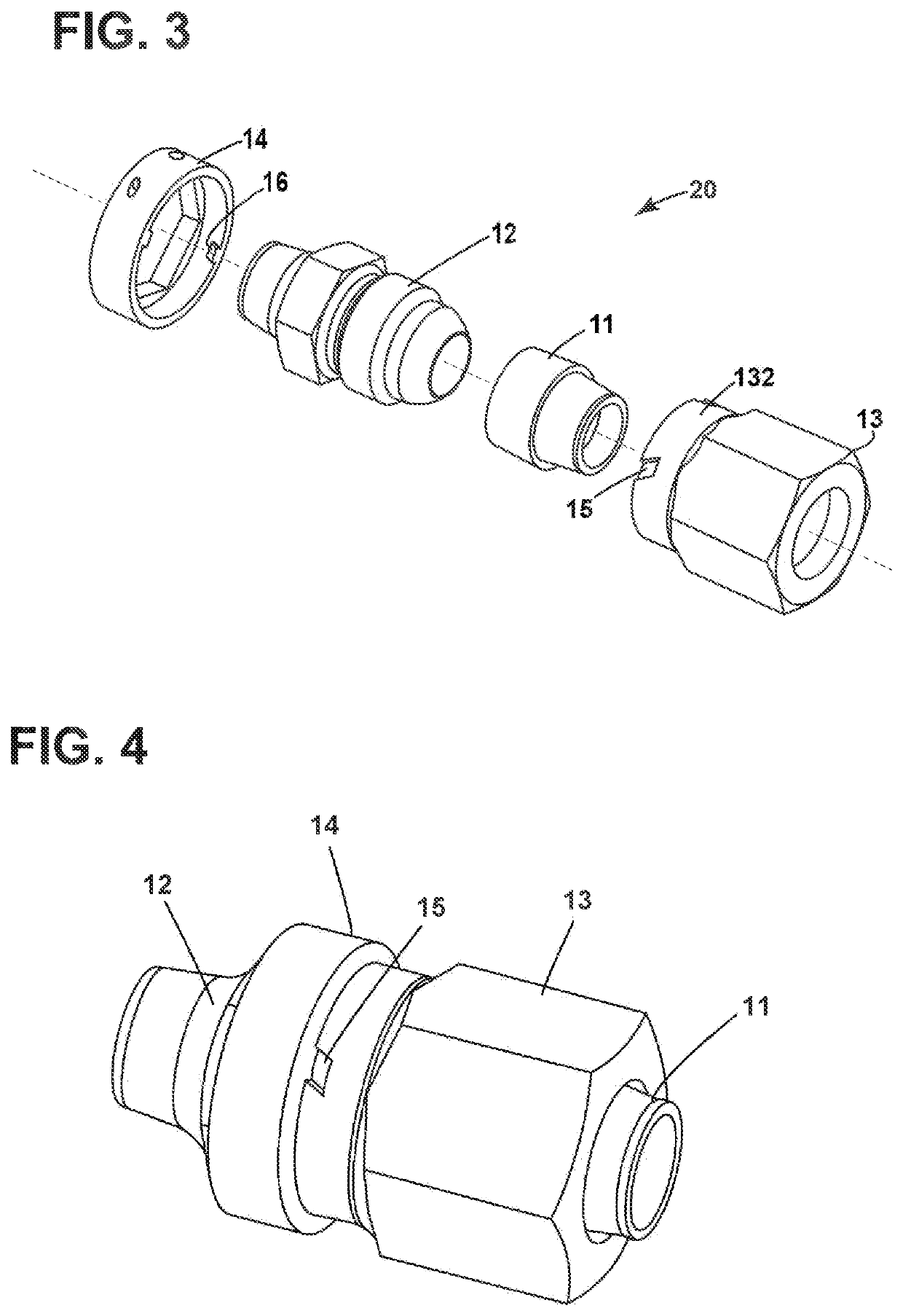
[0017]Embodiments of the present disclosure will be described herein below with reference to the accompanying drawings. In the following description, well-known functions or constructions are not described in detail to avoid obscuring the disclosure in unnecessary detail.

[0018]Unless defined otherwise, technical and scientific terms used herein have the same meaning as is commonly understood by one of ordinary skill in the art to which this disclosure belongs. The terms “first,”“second,” and the like, as used herein do not denote any order, quantity, or importance, but rather are used to distinguish one element from another. Also, the terms “a” and “an” do not denote a limitation of quantity, but rather denote the presence of at least one of the referenced items. The terms such as “front,”“back,”“bottom,” and / or “top,” unless otherwise noted, are merely used for convenience of description, and are not limited to any one position or spatial orientation. The term “or” is meant to be i...


PUM


Abstract

A tube coupling assembly is disclosed, which comprises a first connector for connecting to a tube; a second connector for jointing with the first connector; a first member is adapted to mount on the first connector and operably affixable to the second connector; and a second member is adapted to mount on the second connector, and is capable of being engaged with the first member to prevent separation between the first connector and the second connector.

Description

BACKGROUND[0001]This disclosure relates generally to a self-locking threaded attachment device for preventing separation of threaded attachment device.[0002]In many circumstances, tubes or pipes are needed to be jointed together for allowing the continuous transmission of the fluids or gases. Usually the tubes or pipes are joined by using thread. In order to prevent undesired separation of the connected tubes or pipes, a safety mechanism needs to be designed for tube coupling.[0003]In one example, gas turbine engines and aircraft engines such as those used for aircraft propulsion necessarily include external tubing systems for delivering fluids, either gases or liquids, from one engine component to another or for connecting an engine component with an aircraft system. These tubing systems may include tube coupling assemblies, of various types, to connect adjacent fluid-carrying tubes or to connect a tube to another engine component.[0004]On aircraft engines, the high pressure hydrau...

Claims


Application Information

Patent Timeline
Patent Type & Authority Patents(United States)
IPC IPC(8): F16L19/00F16L27/04F16L37/252
CPCF16L19/005F16L27/04F16L37/252
Inventor JANKIN, GREEDARAN KUBENDRANCHAUDHARI, VINOD SHASHIKANTJONNALAGADDA, DATTU G. V.KUMAR, SANDEEPSIVAPRASAD, RACHAMADUGUREDDY KOLLAM, RAMANASEBASTIAN, MERIN
Owner GENERAL ELECTRIC CO
Features
  • R&D
  • Intellectual Property
  • Life Sciences
  • Materials
  • Tech Scout
  • Unparalleled Data Quality
  • Higher Quality Content
  • 60% Fewer Hallucinations
Learn More