Damper assembly that opts to open doors for usage with reciprocating door closer devices

Inactive Publication Date: 2001-07-12
ALONSO RICARDO
View PDF0 Cites 45 Cited by
  • Summary
  • Abstract
  • Description
  • Claims
  • Application Information

AI Technical Summary

Problems solved by technology

FIG. 10 is a prior art door closer device providing a damper assembly adapted on the

Method used


Image

  • Damper assembly that opts to open doors for usage with reciprocating door closer devices
  • Damper assembly that opts to open doors for usage with reciprocating door closer devices
  • Damper assembly that opts to open doors for usage with reciprocating door closer devices

Examples


Embodiment Construction

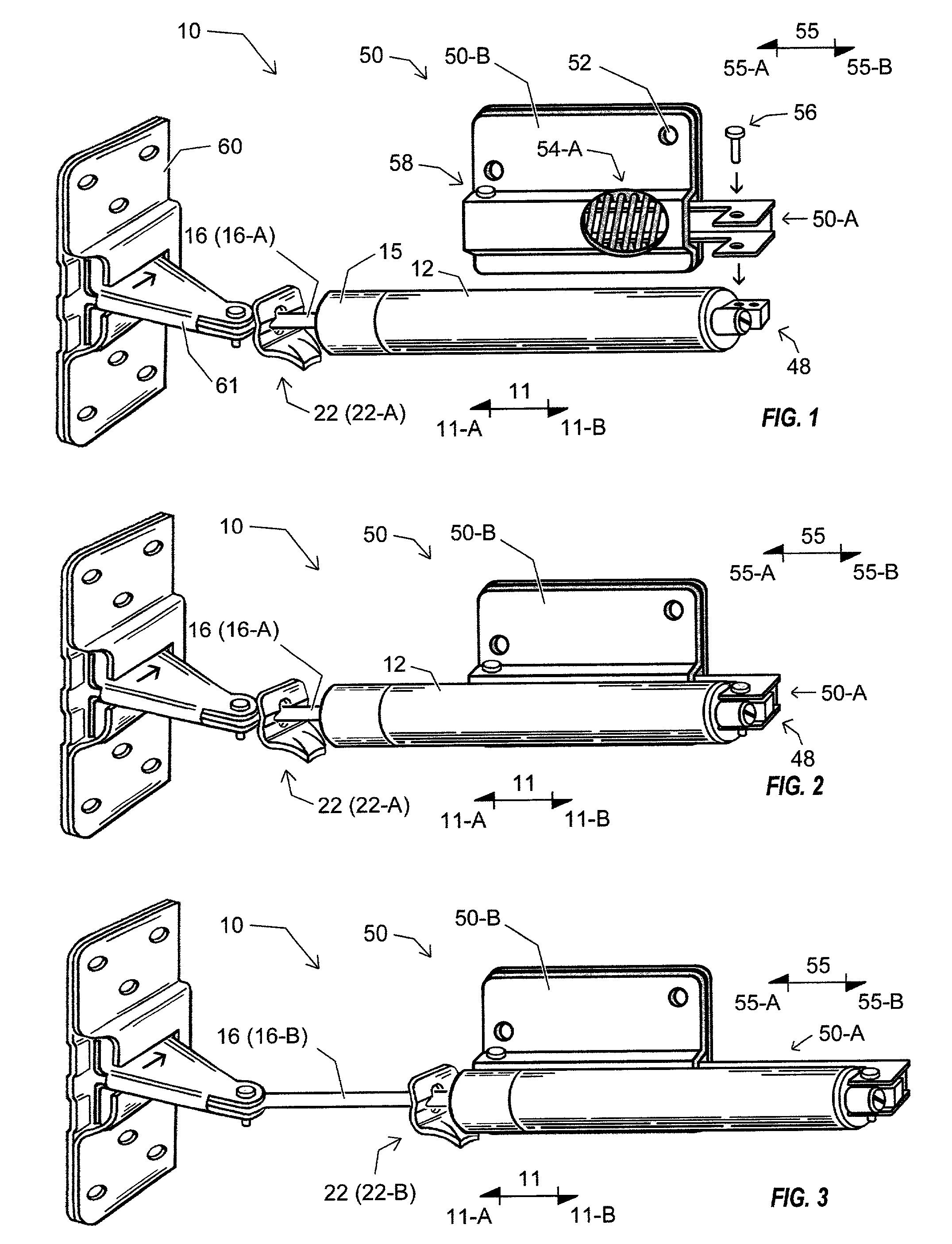
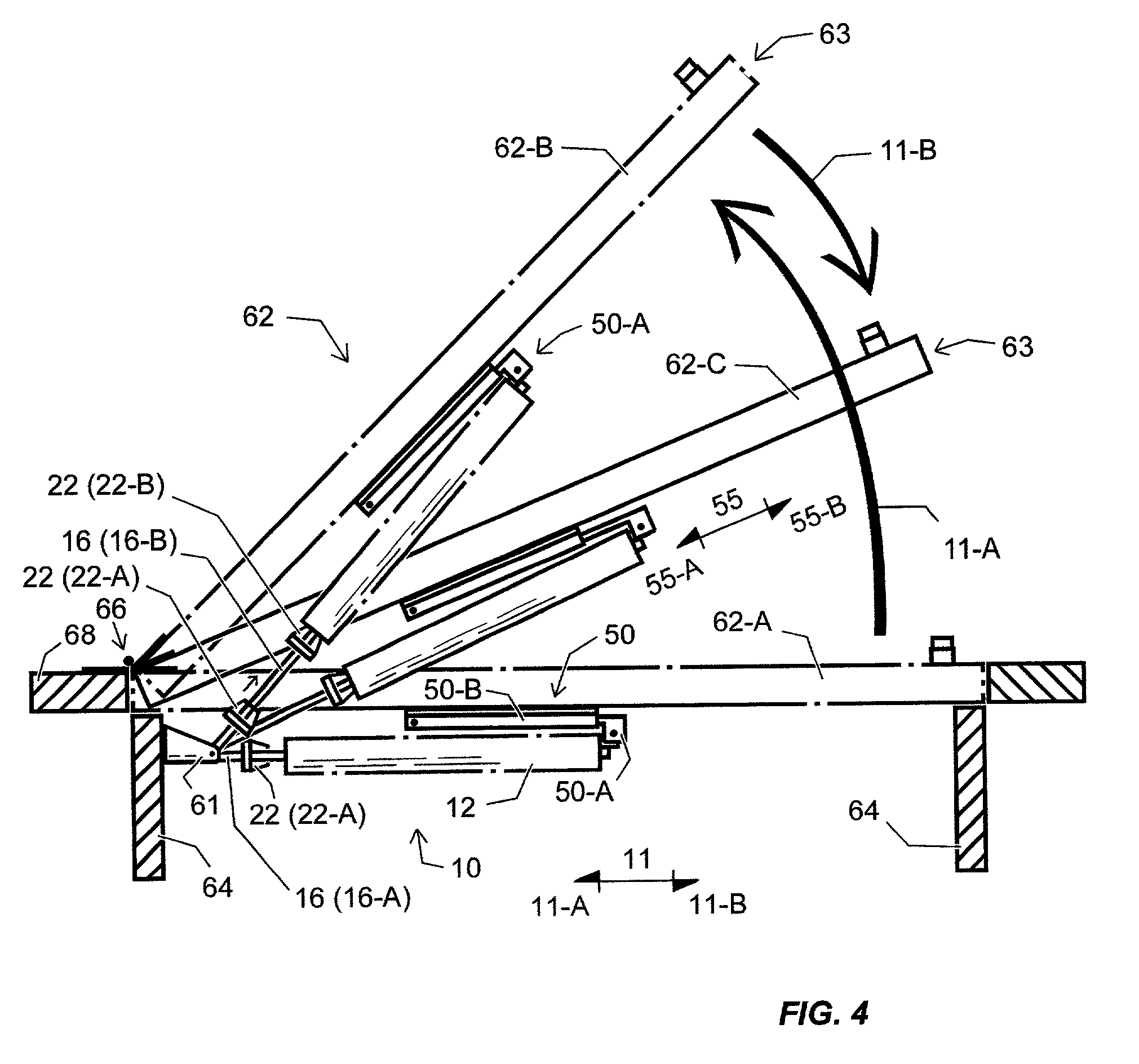
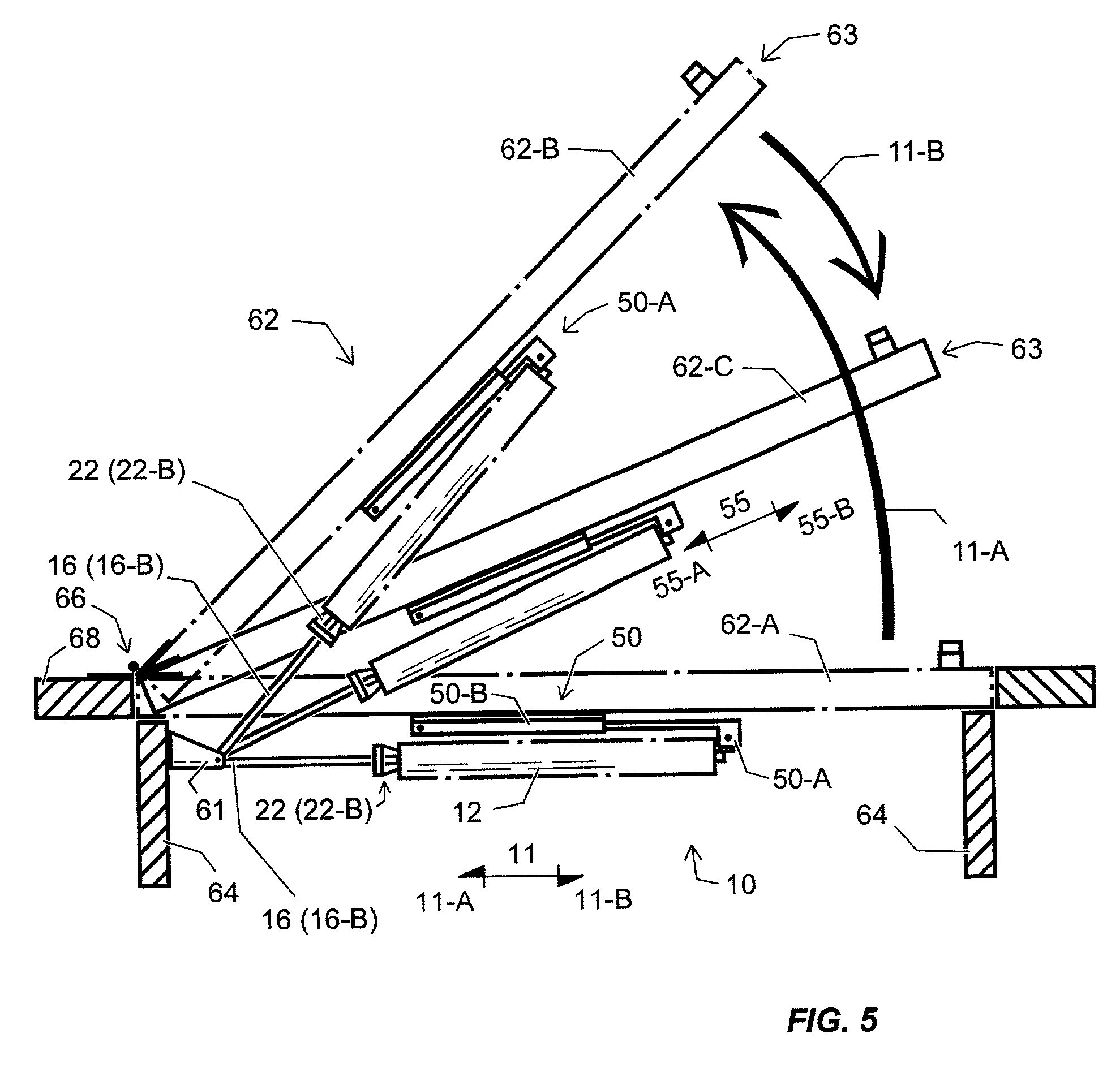
[0026] FIGS. 1-5 are taught conceptually together wherein FIG. 1 is a prospective view of a superior door closer device 10 comprising a piston rod 16 functions from within a piston body 12 controlling a biasing means 11. A superior, substantially tempered and hardened checking mechanism 22 shown in an idle position 22-A is mounted onto the piston rod 16 shown in the retracted position 16-A. A clip plate 60 is accommodating the doorjamb bracket 61 which normally mounts atop a doorjamb (not shown). The invention, a damper assembly 50 is positioned to mount onto the device 10 at the lug mount 48 using a lug pin 56 or similar fastener. The assembly 50 comprises a fixated bracket 50-B providing offsetting fasteners holes 52 for universal left and right attachment to a contingent door 62, shown in FIG. 4, and an extensible bracket 50-A which attaches to the mount 48 of the body 12. A cutout window illustrates that the extensible bracket 50-A is controlled by a spring operator 54-A capable...


PUM


Abstract

A damper assembly (50) adapted to a reciprocative door closer device (10) and contingent door (62), the device (10) comprising a piston rod (16) which functions reciprocatively from within a piston body (12) controlling a biasing means (11); the rod (16) normally loosely mounted with a checking mechanism (22) for variably holding both the rod (16) in an extended position (16-B) and a door (62) in an open position (62-B); the assembly (50) comprising a fixated bracket (50-A) with an offsetting fastener means (52) for universal attachment to left and right hinging doors (62), and, similar to the reciprocative device (10), the assembly (50) comprising an extensible bracket (50-A) controlling a counter biasing means (55) by use of an operator (54) selected from a group including a spring operator means (54-A) that acts to dampen, counter, and protect the device (10) and the door (62) from damage due to excessive inward biasing forces (11-B), and, acts to compensate for a superior checking mechanism (22) such as when the extended rod (16-B) is being held with the engaged mechanism (22-B) and the opened door (62-B) is moved towards the closed position (62-A) without first disengaging the mechanism (22-B), which, simultaneously now commissions the device (10) to return the door (62) to the exact opened position (62-B) determined by the engaged mechanism (22-B) holding the extended rod 16-B.

Description

[0001] This is a continuation-in-part of Ser. No. 09 / 473,822 filed on Dec. 28, 2000.[0002] This invention relates to various reciprocative devices comprising a rod that functions from within a body controlling a biasing means. A reciprocating door closer installed on a contingent screen or storm door exemplifies such a device. To close the door, the rod reciprocates responsive to the biasing means controlled by the device. The rod is normally loosely mounted with a checking mechanism for holding the door in an opened position. Utilizing the biasing means, the mechanism simultaneously engages the closer rod and the body to transpose the biasing means into friction pressure applied to the surface of the rod. Resultantly, the door is held in an opened position by the checking mechanism. More particularly, this invention relates to an improved apparatus and methodology to dampen, counter, and protect the device and the contingent door from damage due to excessive inward biasing forces, ...

Claims


Application Information

Patent Timeline
IPC IPC(8): E05F3/10E05F3/22E05F5/00
CPCE05F3/108E05F3/221E05F5/00E05Y2900/132Y10T16/56Y10T16/593Y10T16/2788Y10T16/27Y10T16/281
Inventor ALONSO, RICARDO
Owner ALONSO RICARDO
Why Eureka
Try Eureka