Cleaning nozzle

Inactive Publication Date: 2001-08-30
SPRAYING SYST DEUTLAND
View PDF0 Cites 19 Cited by
  • Summary
  • Abstract
  • Description
  • Claims
  • Application Information

AI Technical Summary

Benefits of technology

0008] Accordingly, in view of the foregoing, a general object of the present invention is to provide a rotating nozzle having

Problems solved by technology

A rate of rotation of the nozzles that is too high impairs the cleaning effect.
If the fluid is not entirely pure or for other reasons contains particles, the particles cannot be deposited between the turbine and the housing and i

Method used


Image

  • Cleaning nozzle
  • Cleaning nozzle
  • Cleaning nozzle

Examples


Example

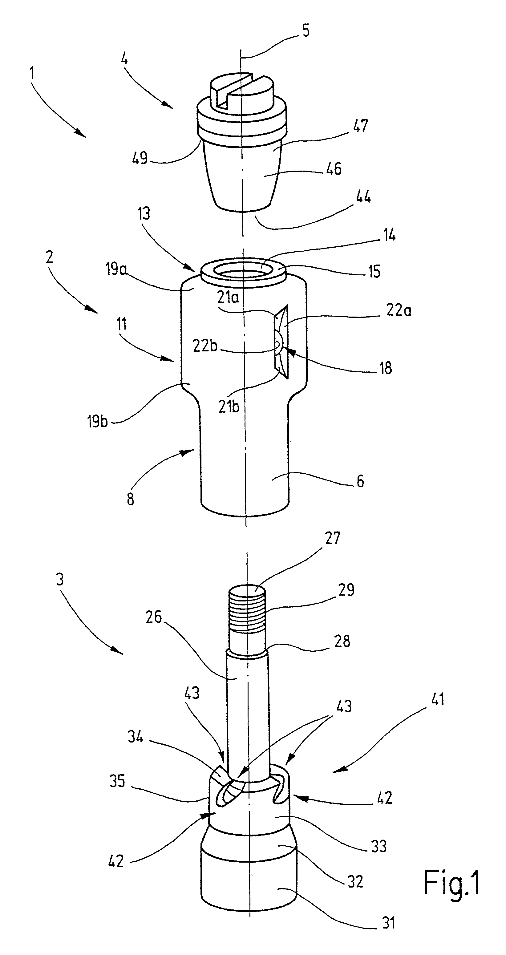
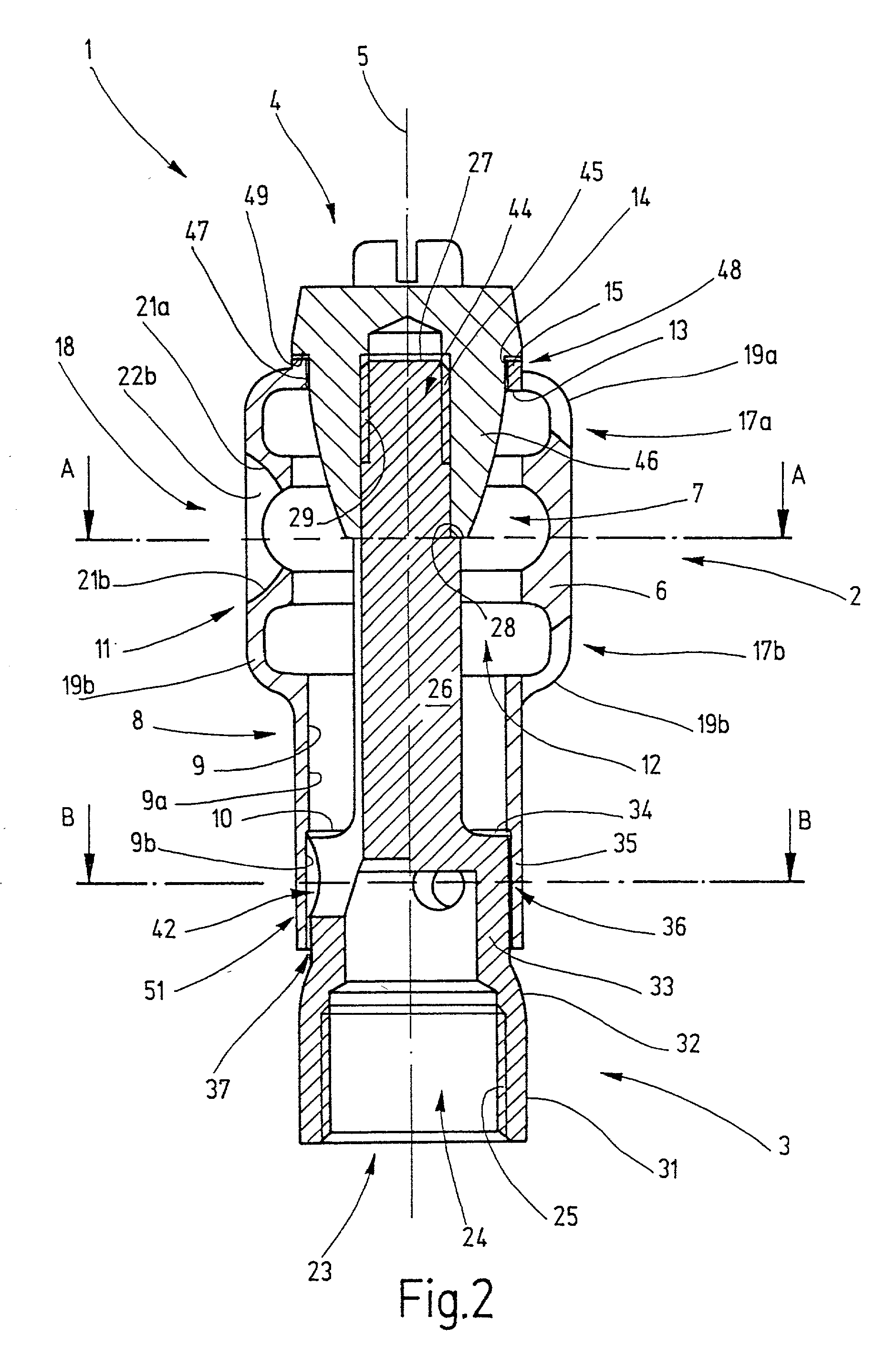
[0036] In FIGS. 1 and 2, a nozzle 1 according to the invention is shown, which serves for generating of a fan-shaped, radially outward-directed discharge jet. The nozzle 1 includes a nozzle body 2, which as shown in FIG. 2, is arranged between a bearing element 3 and a securing element 4 and on which the nozzle body is rotatably supported.

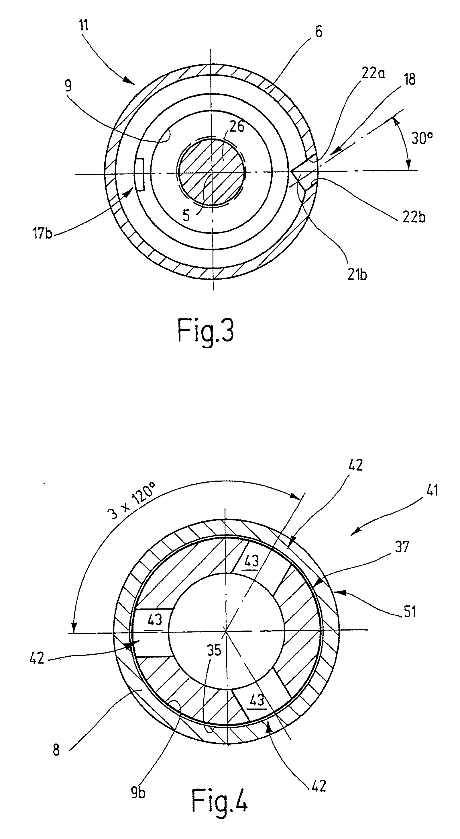
[0037] The nozzle body includes a cylindrical housing 6 that is substantially rotationally symmetrical with respect to the rotation axis 5 and includes a cylindrical interior space 7. On a first end facing away from the securing element 4, the housing 6 is constructed as a tubular neck 8 with a cylindrical inner circumferential surface 9. A radially inward-projecting shoulder 10 divides the cylindrical inner circumferential surface 9 into a first cylindrical section 9a and a second section 9b, which forms the free end of the neck 8 and has a somewhat larger inside diameter with respect to the section 9b.

[0038] The neck 8 transitions into a section ...


PUM


Abstract

A nozzle for use in cleaning applications is provided. The nozzle has a rotatably supported nozzle body, on which one or more nozzle orifices are provided. The nozzle housing itself serves as the rotary drive, which is carried along by a fluid led into the housing with torque. In order to stabilize the drive action, at least one braking device is provided on the nozzle which generates a braking torque by fluid action, preferably through the recoil on a nozzle opening.

Description

[0001] The invention relates to a spray nozzle which can be used especially for cleaning the inner walls of containers, tanks and the like. More particularly, the invention relates to such a cleaning nozzles which rotates in operation, and in which the fluid flowing through serves to drive the rotation.[0002] On the one hand, cleaning nozzles should already be capable of operating under low working pressures, for example from approximately 0.5 bar. On the other hand, the nozzles should not have too high a rate of rotation when higher operating pressures are used, for example pressures above 20 bar. A rate of rotation of the nozzles that is too high impairs the cleaning effect.[0003] A nozzle that rotates in operation and is driven by a fluid is known from BE-A 720 408. The nozzle has a cylindrical housing in which a hollow shaft is rotatably supported by ball bearings. The upper end of the hollow shaft is arranged with an axial connection which serves for feeding a fluid. On the low...

Claims


Application Information

Patent Timeline
IPC IPC(8): B05B1/04B05B3/00B05B3/04
CPCB05B1/04B05B3/003B05B3/0427B05B3/06
Inventor FELLER, ROLANDSTEINHILBER, ERNST
Owner SPRAYING SYST DEUTLAND
Why Eureka
Try Eureka