Printing apparatus and a control method therefor
- Summary
- Abstract
- Description
- Claims
- Application Information
AI Technical Summary
Benefits of technology
Problems solved by technology
Method used
Image

Examples
first embodiment
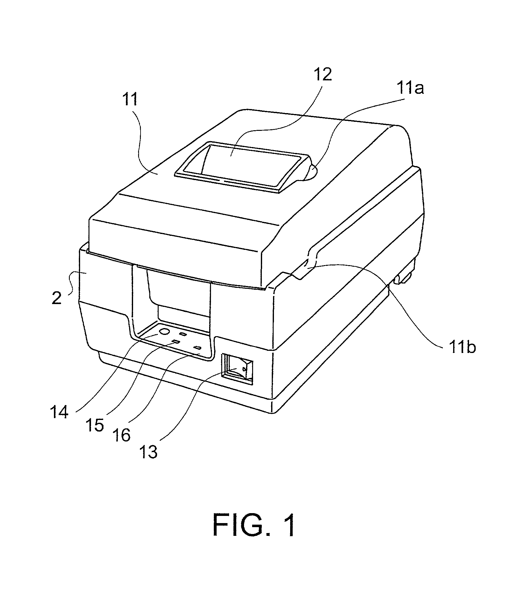
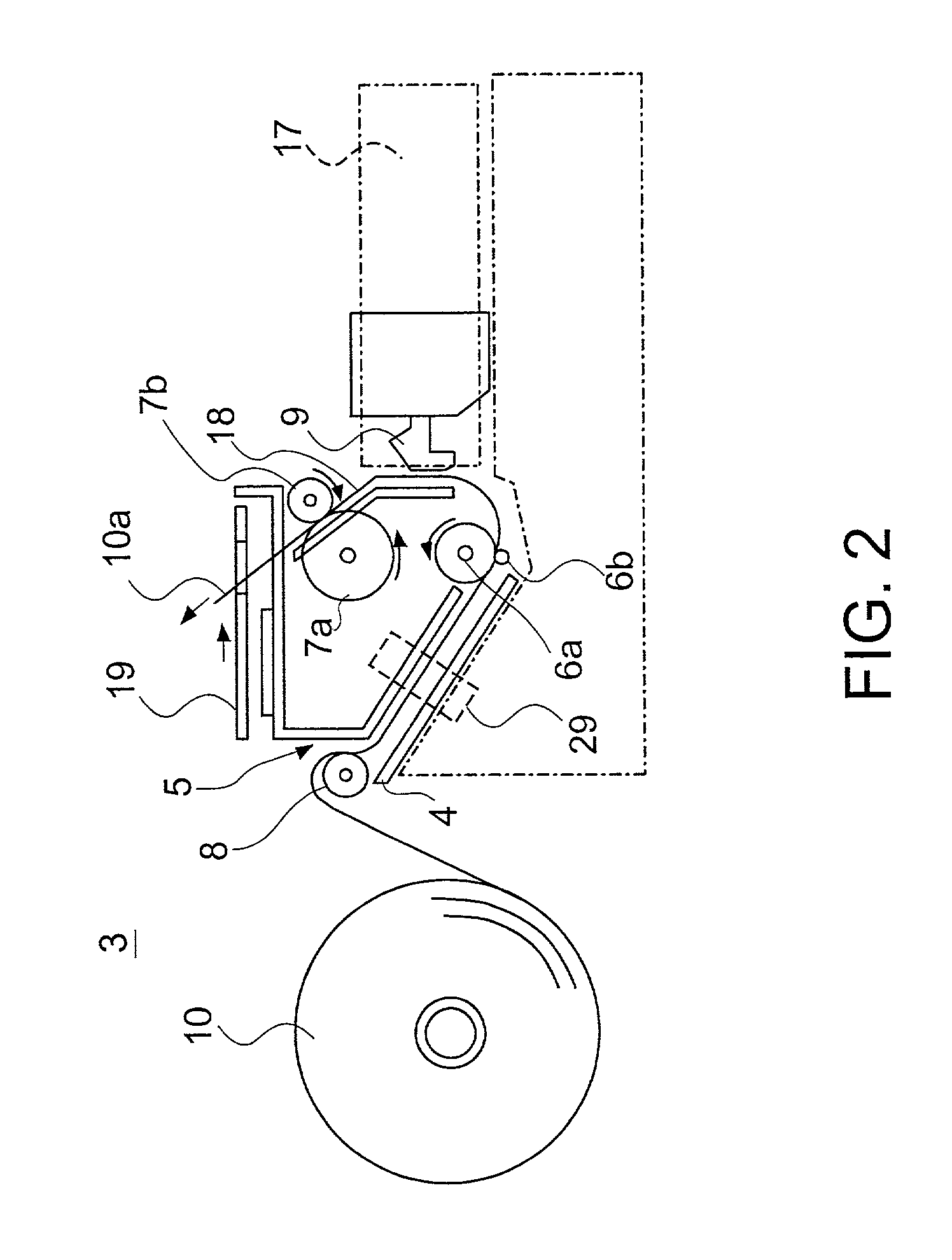
[0063] FIG. 1 is a perspective view of a printer 2 according to the present invention. Printer 2 comprises, as shown in FIG. 2, a paper transportation mechanism for transporting the roll paper by means of a stepping motor (not shown) and paper transport rollers 7a and 7b, a print assembly for printing to the roll paper 10 by means of ink ribbon 17 and print head 9, and a conventional paper-end sensor comprising for example a photo interrupter, lever switch, or other detection mechanism.
[0064] Referring back to FIG. 1, printer 2 further comprises a cover 11 to prevent the operator from accidentally touching the print assembly. Cover 11 can be opened by lifting up on the front edge near printer operating panel 16, thus rotating cover 11 up on a hinge (not shown) disposed at the opposite end and exposing the inside of the printer. An opening 12, through which the roll paper is ejected after printing, is disposed in the middle of the cover 11. When printer 2 is used for printing receipt...
second embodiment
[0092] While the first embodiment has been described using paper-end sensor 29 to detect the presence of a specific consumable material, i.e., roll paper 10, the present invention shall not be so limited. It is also possible to use a near-end sensor to detect a particular remaining amount of roll paper 10, a ribbon sensor to detect how much ink ribbon remains, or a remaining ink detector to detect how much ink remains in the ink cartridge of an ink jet printer.
[0093] Replacement of the ink cartridge is described next below by way of example as another consumable material. Note that further description of steps identical to those used in the roll paper replenishing process is omitted below.
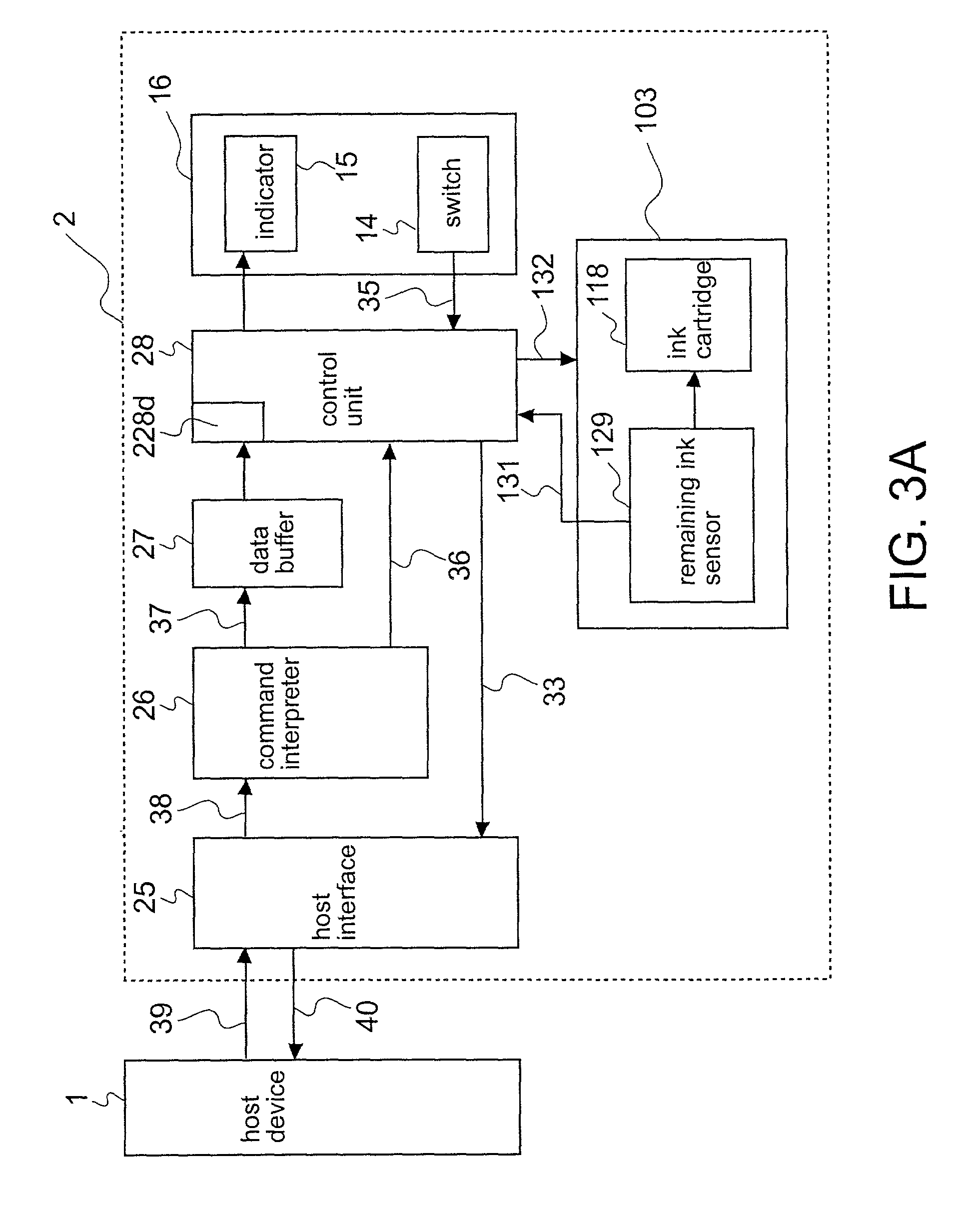
[0094] The print mechanism of the present embodiment is designed to print to roll paper using an ink jet head disposed at the end of the ink cartridge. A remaining-ink sensor for detecting how much ink is left in the ink cartridge is disposed in proximity to the ink cartridge. Note that the remaini...
third embodiment
[0107] As described above, the present invention provides for a printer that goes off-line when the remaining amount of selected consumable materials is detected by means of sensors to have dropped below certain levels an effective method and apparatus for informing the printer without using dedicated switches that the depleted consumable materials have been replenished. It will also be obvious that those skilled in the related art can by making the necessary adaptations to the first and second embodiments described above apply the present invention to all consumable materials used by such a printer.
[0108] The processes executed when it is detected that consumable printer parts or supplies are depleted or nearly depleted have been described above, but it should be noted that the following problems may occur depending upon the operating environment and field of application when a dedicated cover opening sensor and switch for selecting the on-line or off-line state are eliminated. Mor...
PUM
 Abstract
Description
Claims
Application Information
 - Generate Ideas
- Intellectual Property
- Life Sciences
- Materials
- Tech Scout
- Unparalleled Data Quality
- Higher Quality Content
- 60% Fewer Hallucinations
Browse by: Latest US Patents, China's latest patents, Technical Efficacy Thesaurus, Application Domain, Technology Topic, Popular Technical Reports.
© 2025 PatSnap. All rights reserved.Legal|Privacy policy|Modern Slavery Act Transparency Statement|Sitemap|About US| Contact US: help@patsnap.com