
Running control device for industrial vehicle

a running control and industrial vehicle technology, applied in the direction of lifting devices, driver input parameters, brake systems, etc., can solve the problems of deterioration of driving operability, difficult operation, and danger of collapse or spillage of loads, and achieve good operation during starting.

Inactive Publication Date: 2006-12-26
KOMATSU UTILITY +1
View PDF5 Cites 19 Cited by
  • Summary
  • Abstract
  • Description
  • Claims
  • Application Information

AI Technical Summary

Benefits of technology

[0007]The present invention was devised with a focus on the abovementioned problem points; it is an object of the present invention to provide a running control device for an industrial vehicle with superior driving operability that allows easy starting into motion or stopping in place on road surfaces that have a slope or step parts.
[0009]In the first aspect of the invention, since the braking force of the brake, the engaging force of the clutch and the engine revolutions are simultaneous controlled merely by controlling the operation amount using the accelerator means, the operability during starting, especially the operability in the case of starting into motion in a state in which the vehicle wheels are riding on an inclined surface, such as starting into motion on a sloping road or the like, is extremely good. Furthermore, as a result of the simultaneous control of the braking force of the brake, engaging force of the clutch and engine revolutions, starting into motion at a very low speed, traveling at a very low speed and stopping at a very low speed can be accomplished by controlling only the operation amount. Accordingly, starting into motion, traveling and stopping can easily be accomplished without causing any collapse of the load or the like. As a result, driving operation of the vehicle is facilitated, and the workability obtained using this industrial vehicle can be greatly improved.
[0011]In the second aspect of the invention, starting of the vehicle into motion can be easily and reliably accomplished, and the vehicle speed can be reliably increased, by simultaneous control of the engine revolutions, engaging force of the forward clutch and reverse clutch and braking force of the brake while the vehicle speed is in the process of rising to a specified first reference speed or greater. Then, once the vehicle speed has risen, a shift can be made to a more mobile running control mode such as vehicle speed control according to the operation amount or the like after the simultaneous control of the braking force of the brake and the engaging force of the clutch is stopped.
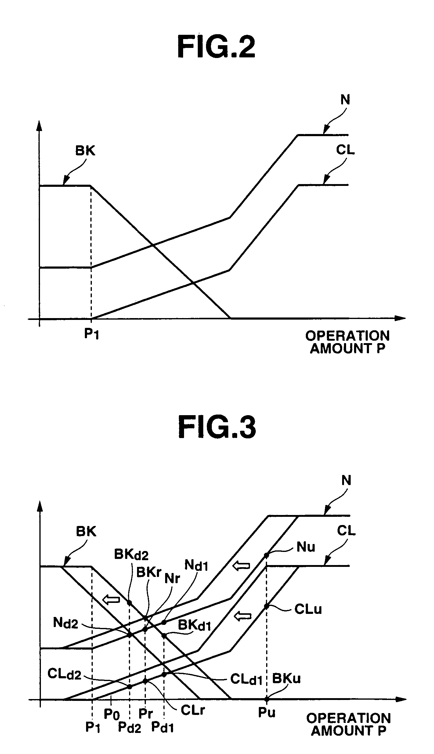
[0013]In the third aspect of the invention, when operation is performed at an operation amount that is equal to or greater than a specified value, even if this operation amount is constant, i.e., even if the operator operates the vehicle while maintaining the same operation amount, the command value curves corresponding to the operation amount are varied so that vehicle driving force generated by the engine revolutions, the engaging force of the forward clutch and reverse clutch and the braking force of the brake that correspond to this operation amount increases; accordingly, the vehicle driving force gradually increases so that the vehicle is eventually started into motion. Consequently, regardless of the conditions of the road surface or sloping road surface that may be involved, the operator can always start the vehicle into motion by operating the vehicle at substantially the same operation amount, so that driving of the vehicle can always be performed with the same operating feeling, thus improving the operability.
[0015]In the fourth aspect of the invention, when the vehicle speed exceeds a specified second reference speed, the variation of the command value curves is stopped, and the respective command values of the engine revolutions, the engaging force of the forward clutch and reverse clutch and the braking force of the brake are determined on the basis of the final command value curves. Accordingly, the increase of the driving force to a value that is greater than necessary contrary to the intention of the accelerator operation of the operator following the starting of the vehicle into motion can be prevented. As a result, there is no discrepancy between the operating feeling of the operator and the actual vehicle speed, so that the operability during starting is good.

Problems solved by technology

However, the following problems occur in the abovementioned prior art.
In such cases, unless the vehicle is started into motion at a very low speed or stopped at a very low speed, there is a danger of collapse or spilling of the load or the like.
Accordingly, operation is extremely difficult, so that the problem of a deterioration in driving operability arises.
Furthermore, such an operation of starting the vehicle into motion at a very low speed or stopping the vehicle in place at a very low speed (so that there is no collapse or spilling of the load) requires a considerable amount of experience.

Method used


Image

  • Running control device for industrial vehicle
  • Running control device for industrial vehicle
  • Running control device for industrial vehicle

Examples


Embodiment Construction

[0024]An embodiment of the present invention will be described in detail below with reference to the attached figures.

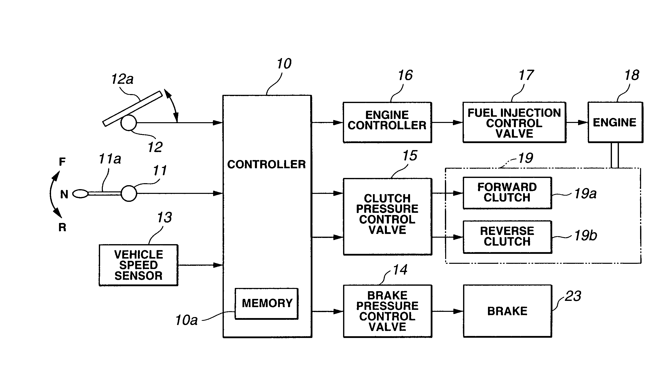
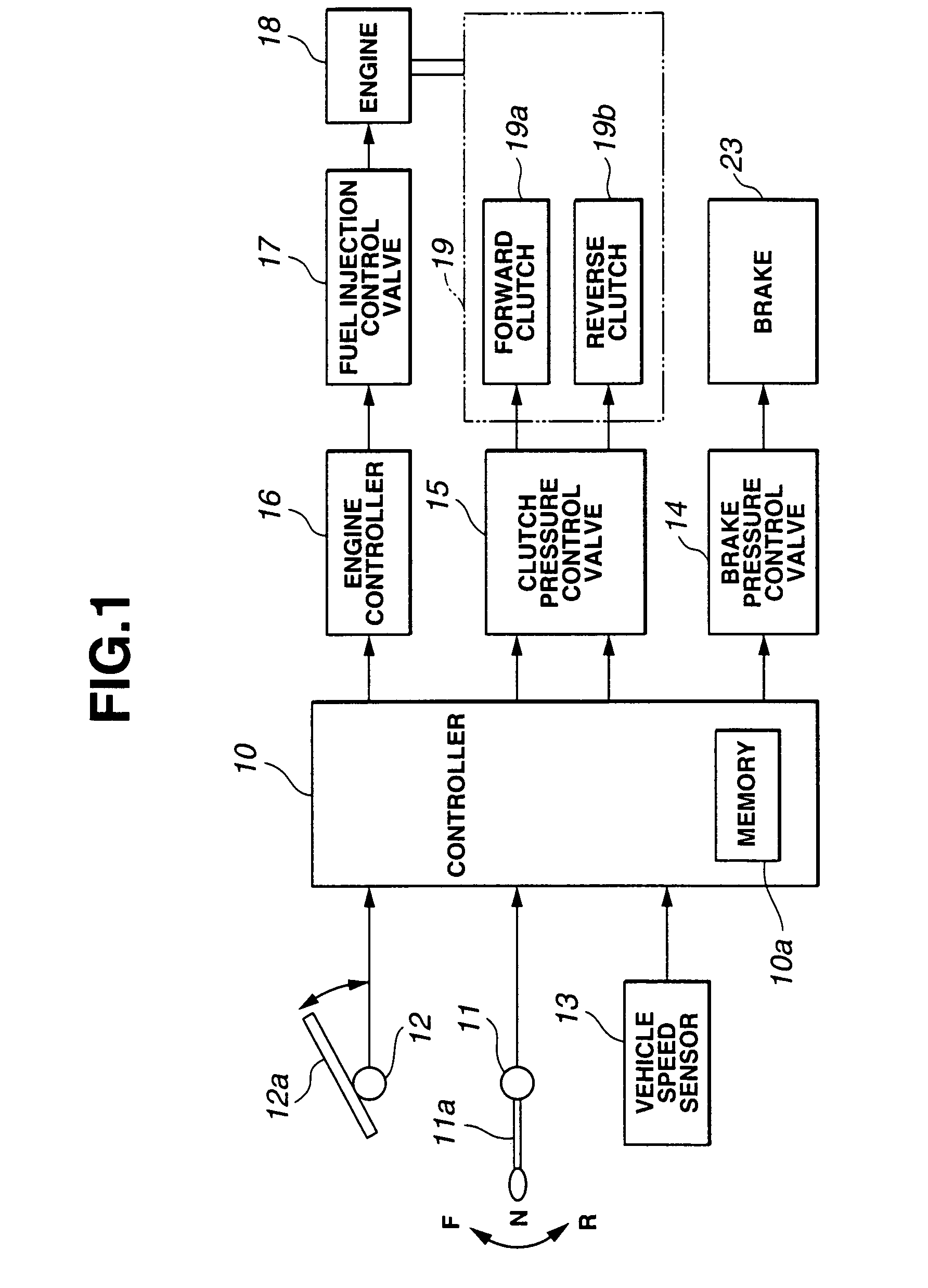
[0025]FIG. 1 is a structural block diagram of a running control device constituting an embodiment of the present invention; the construction of this running control device will be described with reference to FIG. 1.

[0026]The forward-reverse selected direction detection sensor 11 detects whether the direction of travel selected by the forward-reverse selection means 11a (e.g., forward-reverse lever or the like) that switch between forward and reverse is the forward direction, reverse direction or neutral, and outputs a detection signal indicating this to the controller 10. For example, this forward-reverse selected direction detection sensor 11 comprises a limit switch, proximity switch or the like.

[0027]The operation amount detection sensor 12 detects the amount of operation of accelerator means such as an accelerator pedal 12a, accelerator lever (not shown in the fi...


PUM


Abstract

The present invention provides a running control device for an industrial vehicle that has superior driving operability and that allows easy starting and stopping on road surfaces that have sloped or stepped surface. The running control device for an industrial vehicle includes an engine, a sensor that detects an operation amount of an accelerator member, a transmission that has a forward clutch and reverse clutch, a brake that applies braking to the vehicle, and a controller. The controller simultaneously controls the engine revolutions, the engaging force of the forward clutch and reverse clutch and the braking force of the brake in accordance with the operation amount.

Description

BACKGROUND OF THE INVENTION[0001]1. Field of the Invention[0002]The present invention relates to a running control device for an industrial vehicle such as a forklift or the like.[0003]2. Description of the Related Art[0004]Industrial vehicles such as forklifts, wheel loaders, bulldozers and the like generally comprise accelerator means such as an accelerator pedal, accelerator lever or the like used to control the engine revolutions, a clutch pedal used to operate the forward clutch and reverse clutch of a transmission that transmits the rotational torque of the engine to the drive shaft, and a brake pedal and brake lever which are used to operate brakes that apply braking to the vehicle. Conventionally, in industrial vehicles with such construction, cases where so-called starting on a slope is performed, or in cases where the vehicle is started into motion in a state in which the vehicle wheels are riding over a step part as shown in FIG. 8, it is necessary to perform the simultan...

Claims


Application Information

Patent Timeline
IPC IPC(8): B60T11/10B60W10/04B66F9/24B66F9/20E02F9/20E02F9/22
CPCB60K41/202B60K41/282B60W10/04B66F9/20E02F9/2025E02F9/2246E02F9/2253B60K41/26Y10T477/78B60K2741/205B60K2741/26B60K2741/283B60W2520/10B60Y2200/15B60Y2200/41F16H2312/02Y10T477/75Y10T477/639Y10T477/745Y10T477/747Y10T477/74Y10T477/743Y10T477/753Y10T477/6388Y10T477/644B60W10/02B60W10/18B60W30/18B60W2300/121B60W2510/0638B60W2540/10B60W30/18027
Inventor TAKAMURA, MASAYUKIKATO, TAKEOMORI, TAKAYUKI
Owner KOMATSU UTILITY
Learn More