
Antenna structure for fixed wireless system

a fixed wireless and antenna technology, applied in the direction of antennas, radiating element housings, electrical devices, etc., can solve the problems of reducing the antenna gain of the antenna

Inactive Publication Date: 2002-01-03
WSOU INVESTMENTS LLC +1
View PDF0 Cites 22 Cited by
  • Summary
  • Abstract
  • Description
  • Claims
  • Application Information

AI Technical Summary

Problems solved by technology

Thus a fixed wireless network enables premises in remote locations, where connection to a fixed network infrastructure is difficult or expensive, to connect to such an infrastructure via a radio link.
Such an arrangement is inflexible due to the fixed gain which is built in at manufacture.
In the latter case, RF cable losses detract from the antenna gain.
Since the 3.4-3.6 GHz band is the favoured residential fixed wireless loop frequency allocation, cable losses can be significant, especially in low cost cables.
At 3.5 GHz cable losses make the implementation of such an antenna prohibitive.

Method used


Image

  • Antenna structure for fixed wireless system
  • Antenna structure for fixed wireless system
  • Antenna structure for fixed wireless system

Examples


Embodiment Construction

[0022] The invention will now be described by way of example to a particular advantageous implementation. It will be understood that the invention is not limited to such an implementation, and may have applicability beyond the example given herein. Where appropriate, modifications to or alternative applications for, the invention are discussed herein.

[0023] The invention is discussed herein with specific reference to an example of a so-called wireless fixed network, which arrangements are also commonly referred to as wireless access systems or wireless local loop. In such arrangements a location, such as a business premises or a residential premises, is provided with an antenna associated with a radio system for connection to a telephony network external to the location. Within the location, the antenna is connected to a fixed telephony system. In residential premises the fixed telephony system may be a single telephone. In a business premises the fixed telephony system may be a tel...


PUM


Abstract

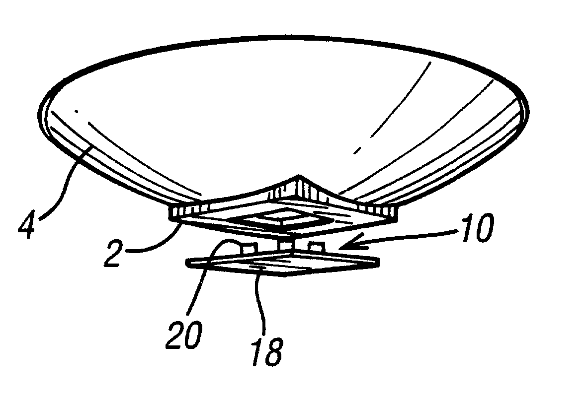
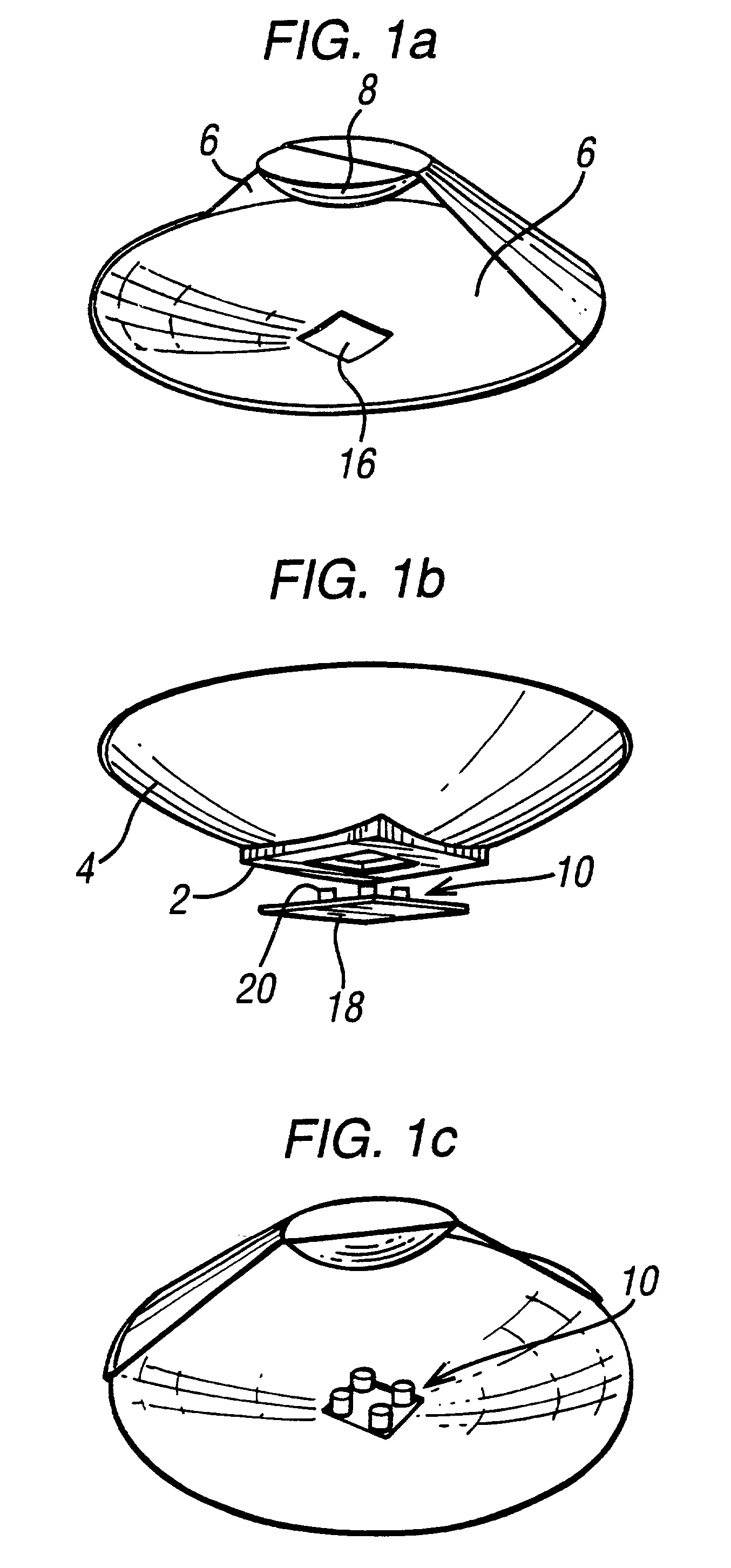
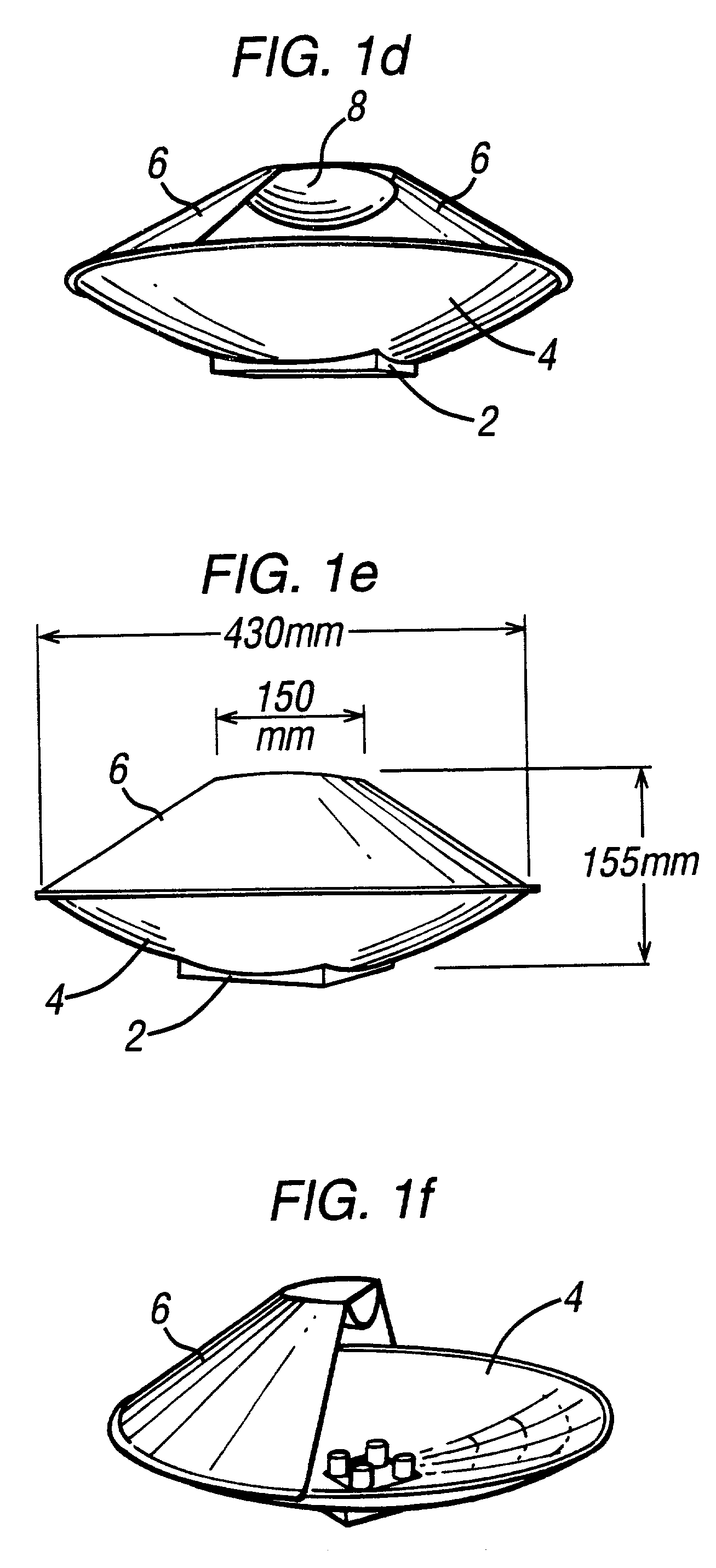
The invention involves a novel mechanical assembly incorporating, in a preferred embodiment, a technically advanced Cassegrain antenna design. The antenna achieves, in experiments, near theoretical performance with the minimum size. The Cassegrain antenna incorporates an intergrated DR array feed.

Description

[0001] This application claims priority of European Patent Application No. 00302053.4, which was filed on Mar. 14, 2000.[0002] The present invention relates to a reflective antenna structure, and particularly but not exclusively to a reflective antenna structure suitable for use in a so-called wireless fixed network.BACKGROUND TO THE INVENTION[0003] In a fixed wireless network a location, such as a business premises or a residential premises, is provided with an antenna associated with a radio system for connection to a telephony network external to the premises. Within the premises, the antenna is connected to a fixed telephony system. In residential premises the fixed telephony system may be a single telephone. In a business premises the fixed telephony system may be a telephone network. Thus a fixed wireless network enables premises in remote locations, where connection to a fixed network infrastructure is difficult or expensive, to connect to such an infrastructure via a radio l...

Claims


Application Information

Patent Timeline
IPC IPC(8): H01Q1/42
CPCH01Q1/42
Inventor AL-RAWI, HAZIM BASHEERFOX, ANDREW JOHNMARTIN, ANTHONY
Owner WSOU INVESTMENTS LLC
Learn More