Arrangement for bearing for a seat

a technology which is applied in the field of arrangement for swinging seats and bearings, can solve the problems of difficult to sense where the desired movement is going to stop, the damping element is not suitable for mounting swinging seats, and the user has a certain feeling of instability, so as to improve the service life and improve the effect of mass production and instooling in different seats

Inactive Publication Date: 2002-04-18
VITRA PATENTE AG
View PDF25 Cites 48 Cited by
  • Summary
  • Abstract
  • Description
  • Claims
  • Application Information

AI Technical Summary

Benefits of technology

[0007] The following features constitute advantageous embodiments of the invention: the spring element is arranged at the top of an axial column of the underframe, preferably on an extensible, axially acting spring. The spring element is intended, in particular, for being arranged at the top of an axially extensible push rod of a pneumatic spring. The spring element has an elastic outer sleeve, e.g. a rubber body. The casing has a bottom, cup-like part in which the spring element is seated. The spring element and the casing have an axial through-passage. Alternatively, the casing, in which the spring element is seated, is a cup-like part which encases the spring element from above.

Problems solved by technology

Either these designs barely provide the desired swinging effect or else the user has a certain feeling of instability and, in the case of deflection, immediately feels that it is harder to sense where the desired movement is going to stop.
Apart from the fact that this damping element, from a totally different field of expertise, has a quite different task--from mounting a seat--such a damping element is not suitable for mounting a swinging seat.

Method used


Image

  • Arrangement for bearing for a seat
  • Arrangement for bearing for a seat
  • Arrangement for bearing for a seat

Examples


first embodiment

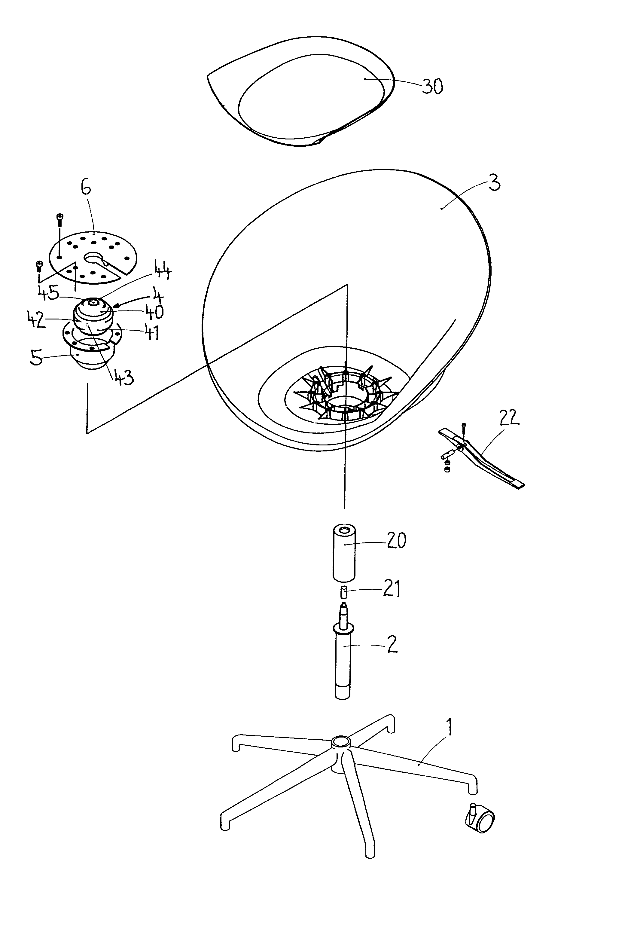
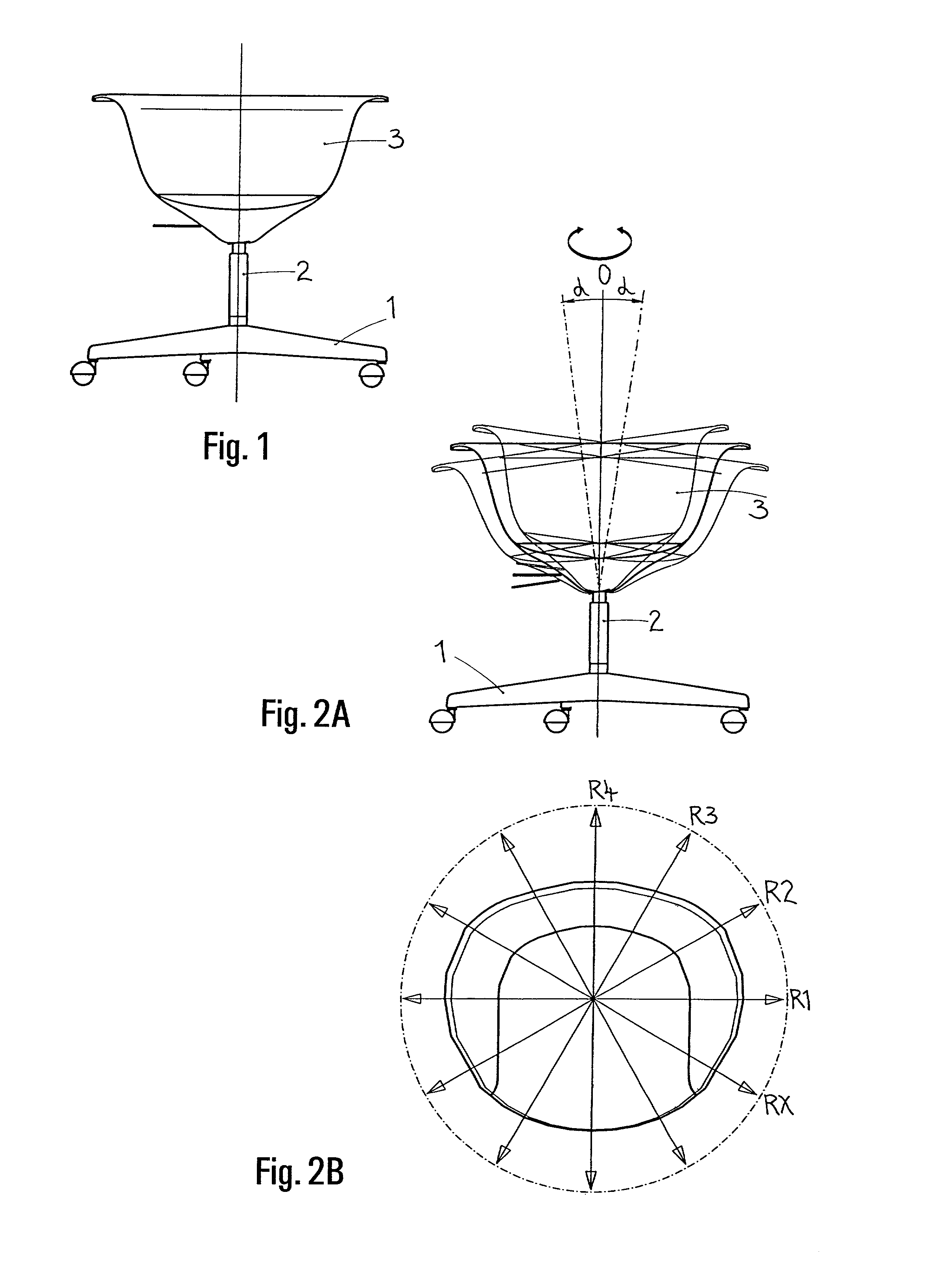
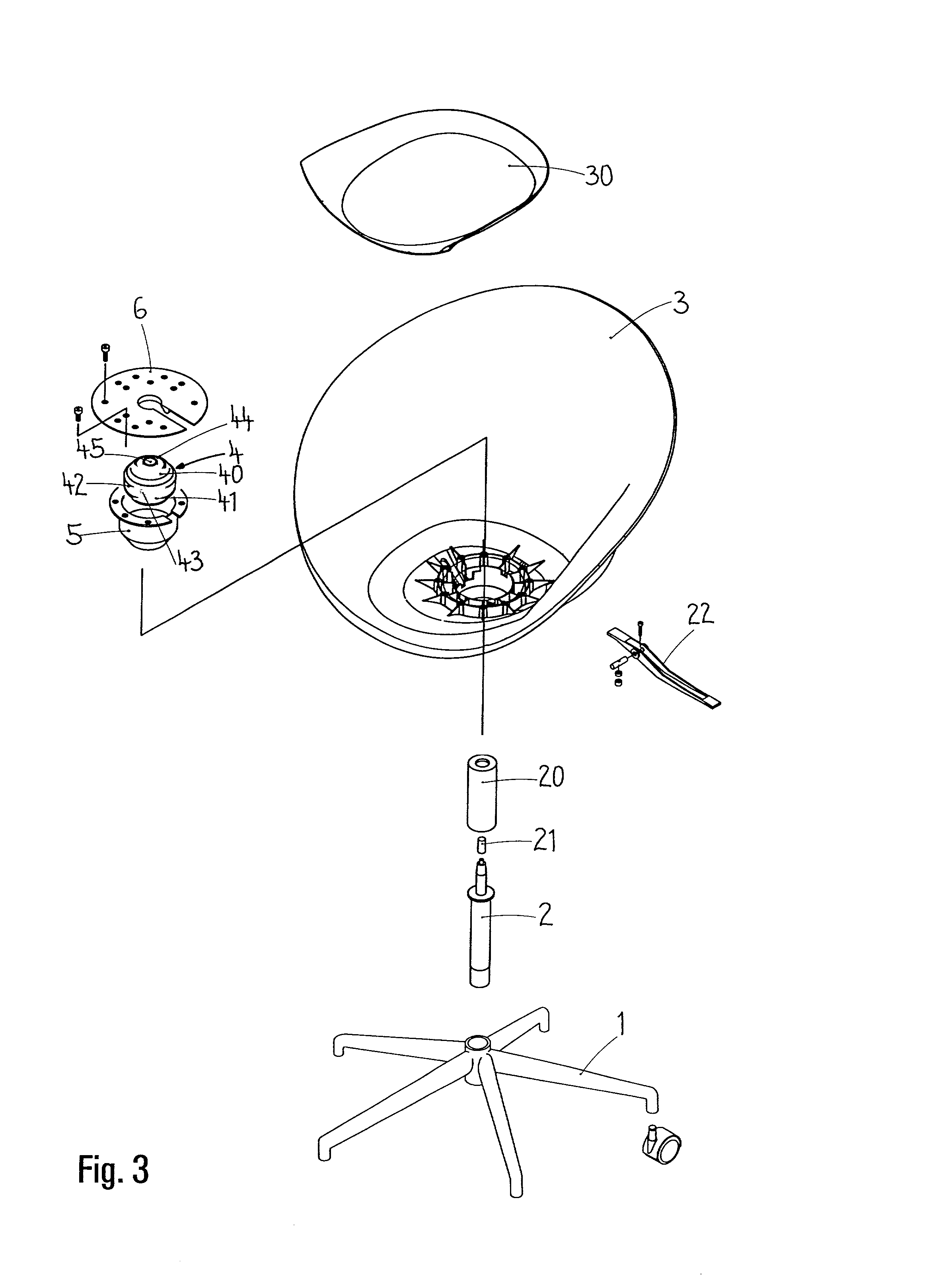
[0037] The underframe 1, the central column 2--typically a pneumatic spring--and a shell-like seat 3 are provided here. It is also possible to see a tubular pneumatic-spring covering 20 and a cylindrical push-rod extension 21. A triggering lever 22 fitted beneath the seat 3 is provided for actuating the pneumatic spring 2. the mounting comprises a first variant of a spring element 4, a bottom, cup-like casing 5 and a top molding 6, in this case in the form of a cover plate which is intended for fastening on the top side of the base of the seat 3. Finally, a seat-cushion panel 30, which covers the top molding 6, is provided. The spring element 4 is roughly cylindrical with reduced-diameter sections 40,41 at the top and bottom, a central section 42, an outer sleeve 43, a core 44 and an axial through-passage 45, the latter running through the core 44.

[0038] FIG. 4A

[0039] In the case of the first embodiment of the mounting, in the instooled state, the first variant of the spring element...

second embodiment

[0048] the seat mounting according to the invention is illustrated here. Once again, an underframe 1, a central column 2--preferably a pneumatic spring--a seat 3, the spring element 4, the bottom casing 5' and a top molding 6' are provided for this chair. The special feature here is that, rather than being formed by a separate plate, the top molding 6' is formed by a correspondingly contoured aperture 60' in the seat carrier 6'. The aperture 60' encloses the top section 40 of the spring element 4 in the same way as the shaped collar 60. The cutout 61' is provided again in the seat carrier 6'. The casing 5' is inserted into the aperture 60' by way of its top border, is enclosed by the seat carrier 6' and is connected to the latter, the spring element 4 being more or less encapsulated in the process. The cutout 61' provides the freedom of movement as deflection from the rest position 0.

[0049] If use is made of the first variant of the spring element 4 (according to FIG. 6A), as is the...

third embodiment

[0051] In the case of this third embodiment of the seat mounting, use is made of a third variant of a spring element 4, which is likewise intended for fitting onto a central column 2. The sheath-like core 44 has an axial through-passage 45 for accommodating the top end of the central column 2, preferably a pneumatic spring with a telescopically extensible lifting rod. It is advantageous if the axial through-passage 45, to complement the lifting rod, narrows conically upward.

[0052] The core 44, consisting, for example, of steel, has an encircling shoulder surface 442, which is preferably produced by an outside cone with a diameter which tapers in an upwardly sloping manner. A conical outer sleeve 43 made of elastic material, e.g. rubber, is arranged on the shoulder surface 442. The outer sleeve 43 is enclosed by a top molding 600, with the result that the latter constitutes a casing 600 for the outer sleeve 43. In order to ensure optimum functioning, the core 44 should be fixed to th...


PUM


Abstract

The mounting for a seat (3) is suitable, in particular, for a chair, but also for stools, individual seats (3) on a bench or fixed seats (3). The mounting makes it possible for the seat (3) to swing resiliently in all directions or in defined directions, in accordance with changes in the user's posture. The seat (3) rests on an underframe on which a spring element (4) is arranged, said spring element being restrained in a casing (5,6) and being capable of moving elastically, in a horizontal plane, therein. The casing (5,6) is connected to the seat (3) or forms a part thereof. The spring element (4) is preferably arranged at the top of an axially extensible push rod of a pneumatic spring (2). The outer sleeve (43) of the spring element (4) is a rubber body, while the axial through-passage (45) of the spring element (4) has a preferably metallic core (44) around it. The specific advantages of the mounting result in improved seating comfort.

Description

[0001] The present invention relates to a mounting for a seat, in particular a chair, but is also suitable for stools, individual seats on a bench or fixed seats in vehicles or, for example, in stadiums or parks. The invention specifically concerns a seat mounting which makes it possible for the seat to swing resiliently in all directions or in defined directions. Such seats follow the user's posture and, beyond the resilient mounting of the seat cushion, give the seat user a freer feeling of swinging action.PRIOR ART[0002] Mountings for seats are known in a wide range of designs. For work chairs, in particular, the capacity for height adjustment and the resilient mounting of the backrest are standard nowadays (see, for example, WO 98 / 16140). Many chairs are equipped with a synchronizing mechanism, as a result of which a movement of the backrest is followed by a simultaneous, synchronous movement of the seat surface. The capacity for height adjustment is brought about mostly by a pn...

Claims


Application Information

Patent Timeline
Patent Type & Authority Applications(United States)
IPC IPC(8): A47C3/026
CPCA47C7/448A47C3/026
Inventor BRAUNING, EGON
Owner VITRA PATENTE AG
Why Eureka
Try Eureka