Adjustable equipment rack

a technology of equipment racks and adjustable brackets, which is applied in the direction of show shelves, electrical apparatus construction details, and support structure mounting, etc., can solve the problems of less room for accessing and storing equipment, significantly more expensive cabinets, and the addition of mounting rails to prior rack posts

Inactive Publication Date: 2002-04-25
ORTRONICS INC
View PDF1 Cites 79 Cited by
  • Summary
  • Abstract
  • Description
  • Claims
  • Application Information

AI Technical Summary

Problems solved by technology

A disadvantage of using equipment cabinets is that such cabinets are significantly more expensive than a four post open rack and provide less room for accessing and storing equipment.
A disadvantage of using prior four post open racks is that the posts in prior racks are also the mounting rails.
Thus, the posts cannot be adjusted to varying depths once the rack is assembled and installed.
In addition, prior four-post racks lack a sufficient range of adjustment to satisfy all installation requirements.

Method used


Image

  • Adjustable equipment rack
  • Adjustable equipment rack
  • Adjustable equipment rack

Examples


Embodiment Construction

)

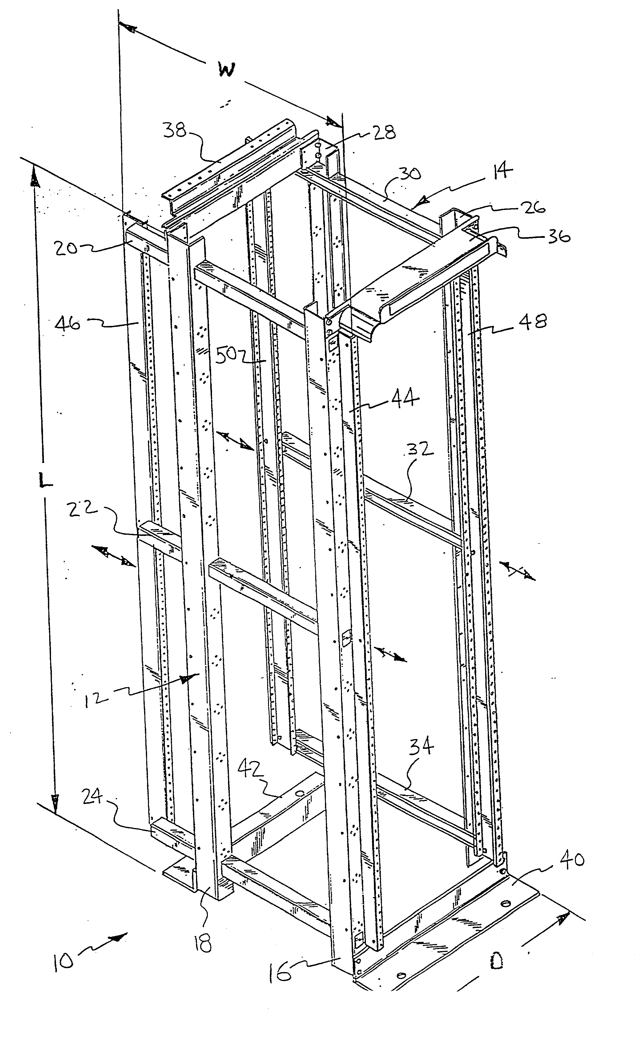
[0014] The following detailed description of preferred and / or exemplary embodiments of the present disclosure is intended to be read in the light of, or in context with, the preceding summary and background descriptions. Unless otherwise apparent, or stated, directional references, such as "up", "down", "left", "right", "front" and "rear", are intended to be relative to the orientation of a particular embodiment of the disclosure as shown in the first numbered view of that embodiment. Also, a given reference numeral should be understood to indicate the same or a similar structure when it appears in different figures.

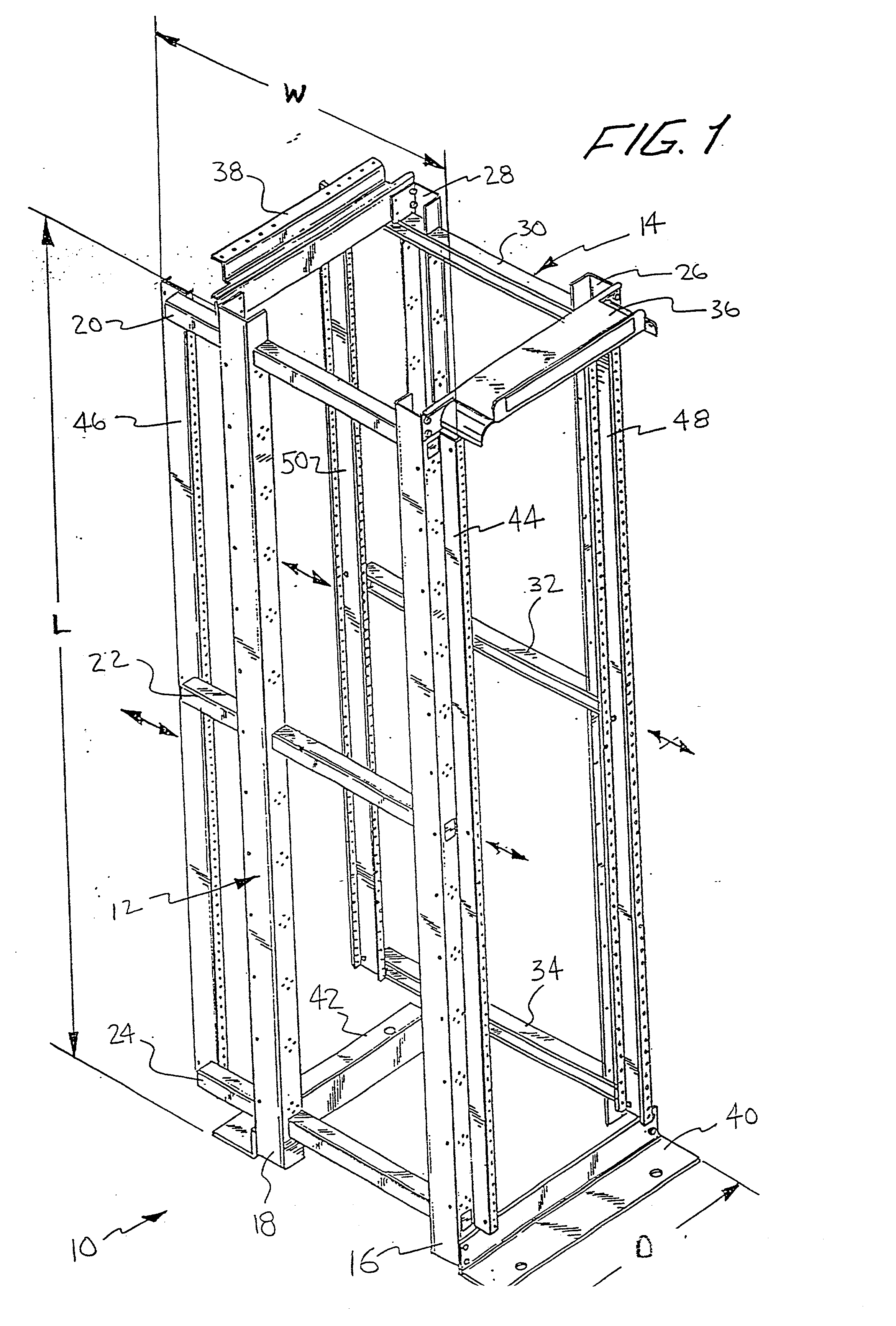
[0015] Referring to FIG. 1, an adjustable equipment rack 10 is illustrated which includes two elongated structural support members, i.e., frame members 12 and 14, respectively. Frame member 12 is referred to herein as the left-hand ("LH") frame and frame member 14 is referred to herein as the right-hand ("RH") frame solely for convenience sake when referring to the orie...


PUM


Abstract

An equipment rack is disclosed having two opposing structural support frames connected by a plurality of elongated beams defining an adjustable interior volume having a length, width and depth therein. Each opposing support frame has at least two posts defining two opposing sides. The posts are connected by a plurality of elongated cross beams which include a portion that extends outwardly from at least one of the opposing sides. At least two opposing rails are slidably mounted on the plurality of elongated cross beams to permit movement of the rails along the longitudinal axis of the elongated cross beams. Thus, the interior volume of the adjustable equipment rack may be adjusted, e.g., expanded by sliding the opposing rails of each opposing support frame along the plurality of cross beams and into the portion of the cross beams extending beyond the posts.

Description

[0001] The present application claims the benefit of a co-pending, commonly assigned provisional patent application entitled "Adjustable Server Rack," filed on Sep. 27, 2000, and assigned Ser. No. 60 / 235,714, the entire contents of which are hereby incorporated by reference.[0002] 1. Field of the Disclosure[0003] The present disclosure relates generally to an adjustable equipment rack and, more particularly, to an equipment rack wherein front and rear equipment mounting rails are adjustable to accommodate electronic equipment of varying sizes, depths and / or configurations.[0004] 2. Background of the Disclosure[0005] Presently, in order to get the benefit of an open rack with equipment mounting rails that are adjustable, a user either has to purchase an equipment cabinet without sides and doors or an old style four post open rack. A disadvantage of using equipment cabinets is that such cabinets are significantly more expensive than a four post open rack and provide less room for acce...

Claims


Application Information

Patent Timeline
Patent Type & Authority Applications(United States)
IPC IPC(8): H05K7/18
CPCH05K7/183H05K7/1488
Inventor LARSEN, LARS R.LEVESQUE, STEWART A.
Owner ORTRONICS INC
Why Eureka
Try Eureka