Electrical interrupt switch

a technology of electrical interrupt switch and switch body, which is applied in the direction of coupling contact member, coupling device connection, electric discharge lamp, etc., can solve the problems of premature failure of plug or receptacle, user shock hazards,

Inactive Publication Date: 2002-05-09
JENKS JERRY A
View PDF0 Cites 24 Cited by
  • Summary
  • Abstract
  • Description
  • Claims
  • Application Information

AI Technical Summary

Problems solved by technology

First, the continual wear and tear on the plug and receptacle from repeated insertions may cause either the plug or receptacle to fail prematurely.
Secondly, the act of inserting a plug allows for a short time period in which the prongs a

Method used


Image

  • Electrical interrupt switch
  • Electrical interrupt switch
  • Electrical interrupt switch

Examples


Embodiment Construction

of the Figures

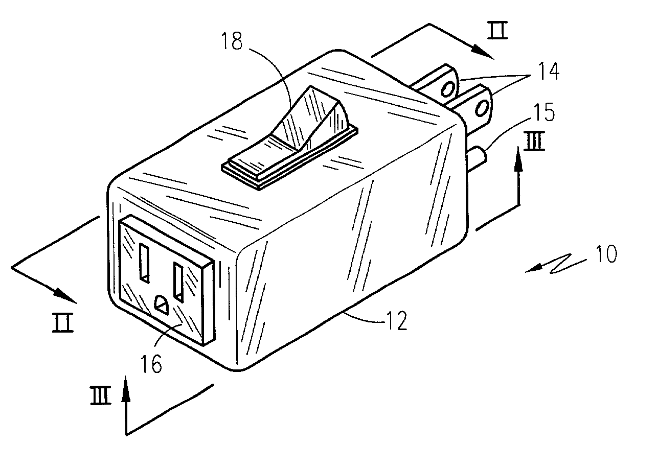
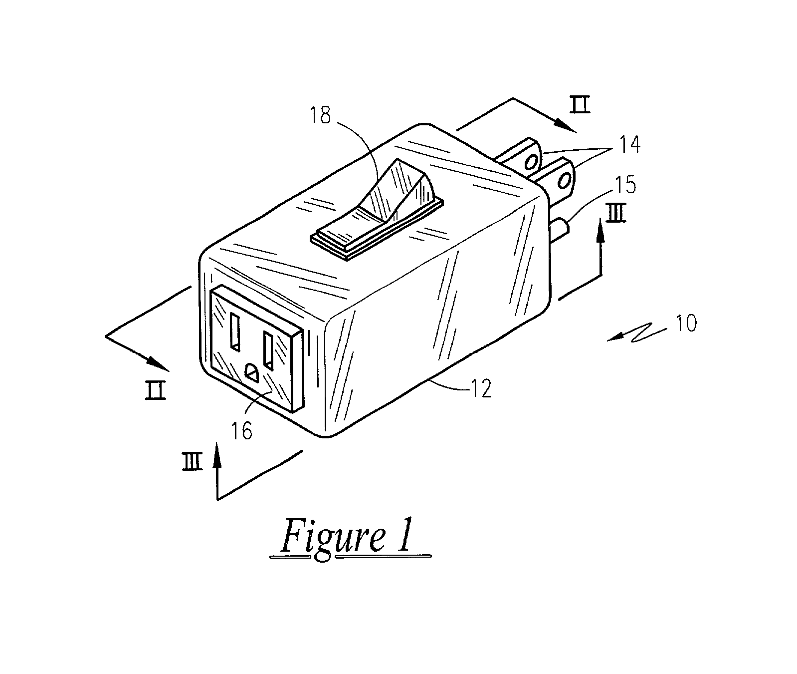
[0030] Referring now to FIG. 1, an electrical interrupt switch 10 is shown, according to the present invention, is provided that allows for the disconnection of electrical plug-connected equipment without removing the plug from the receptacle. It is anticipated that such a switch 10 could be made available for use on grounded or ungrounded electrical systems. The switch 10 has a housing 12 that has a compact overall outer dimension approximately one inch high, one inch wide and three inches long. Extending outward from one end of the housing 12 are male blade connectors 14 sized for a standard 120 VAC plug which connects to common 120 VAC outlets found in homes and business. Additionally, a ground prong 15 could be made available depending on the model. Opposite the blade connectors 14 are corresponding receptacle connectors 16 to allow for the connection of a conventional electrical power cord. Accessible through the upper portion of the housing 12 is a rocker switch ...


PUM


Abstract

An electrical circuit interrupter for a conventional electrical plug is provided that be mounted on a wall electrical socket or on the plug itself. Adaptable to either 2-prong or 3-prong electrical plugs, a toggle switch either turns on or off the circuit from the plug to the wall socket.

Description

[0001] The present invention is a continuation of U.S. Provisional Patent No. 60 / 196,859 filed on Apr. 12, 2000.[0002] 1. Field of the Invention[0003] The present invention relates generally to electrical switches and, more particularly, to a general purpose, consumer electrical interrupt switch[0004] 2. Description of the Related Art[0005] There are many electrically powered items in our homes and businesses which do not have an on / off switch. These include some kitchen appliances, tools, Christmas lights and the like. There are also some items with power switches that still utilize power when in the off position. These include televisions, computers, VCR's and other electronic items. The only way to completely remove electrical power from all of these devices is to remove the electrical power cord from the receptacle. This however, has several disadvantages. First, the continual wear and tear on the plug and receptacle from repeated insertions may cause either the plug or receptac...

Claims


Application Information

Patent Timeline
IPC IPC(8): H01R13/70H01R31/06
CPCH01R31/065H01R13/70
Inventor JENKS, JERRY A.
Owner JENKS JERRY A
Why Eureka
Try Eureka