Self-supporting cable and manufacturing method therefor

a self-supporting cable and manufacturing method technology, applied in the direction of cables, insulated conductors, instruments, etc., can solve the problem of no clearance between the outer cover layer and the cabl

Inactive Publication Date: 2002-05-30
SUMITOMO ELECTRIC IND LTD
View PDF2 Cites 94 Cited by
  • Summary
  • Abstract
  • Description
  • Claims
  • Application Information

AI Technical Summary

Problems solved by technology

In addition, when the outer cover layer is formed in the extrusion process,...

Method used


Image

  • Self-supporting cable and manufacturing method therefor
  • Self-supporting cable and manufacturing method therefor
  • Self-supporting cable and manufacturing method therefor

Examples


Embodiment Construction

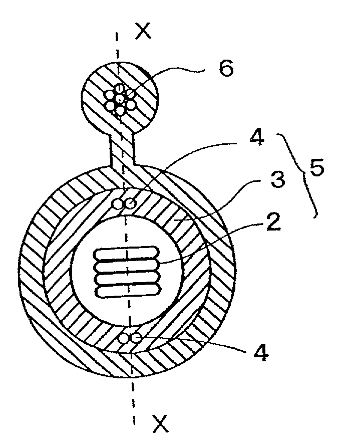
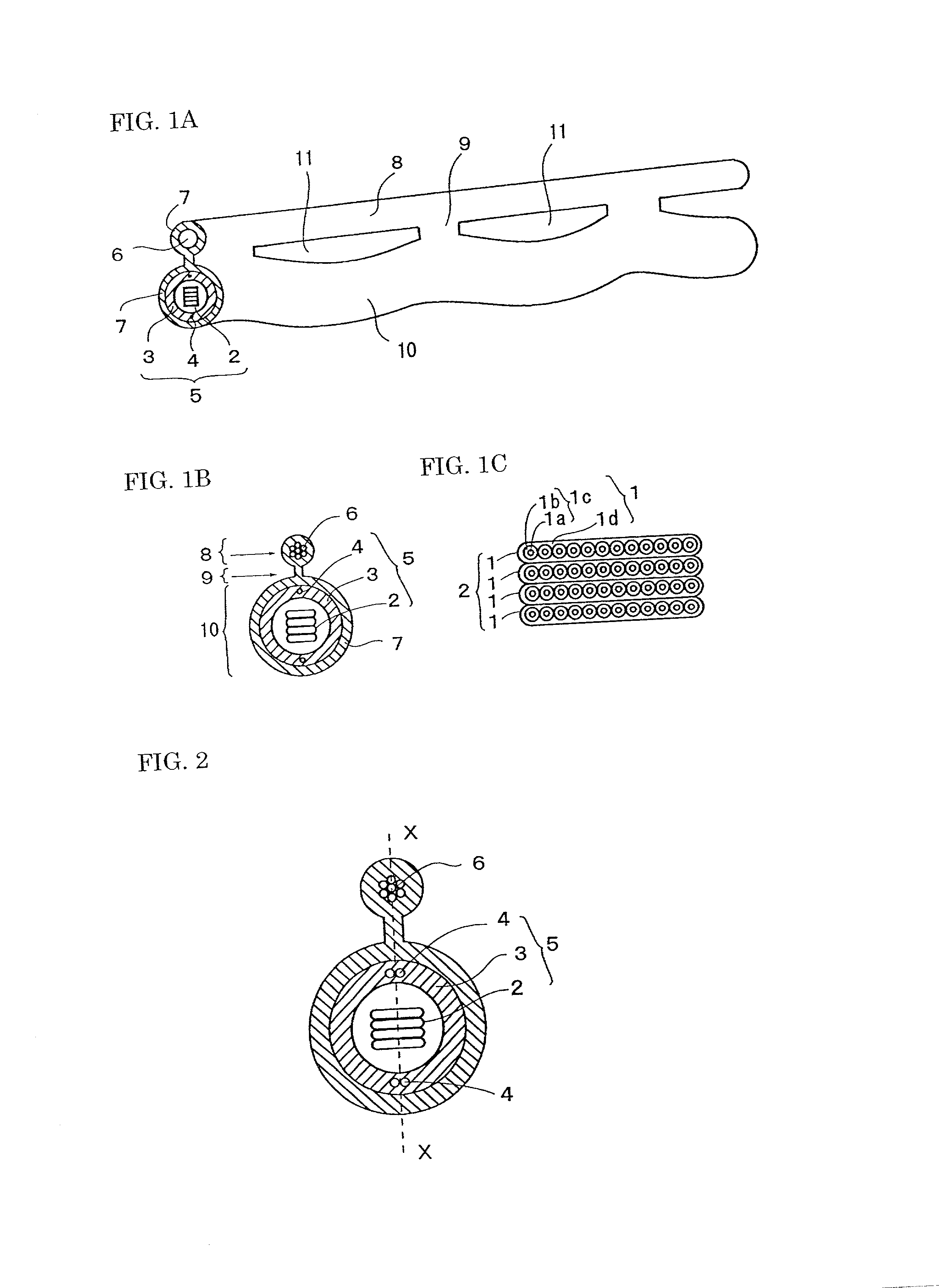
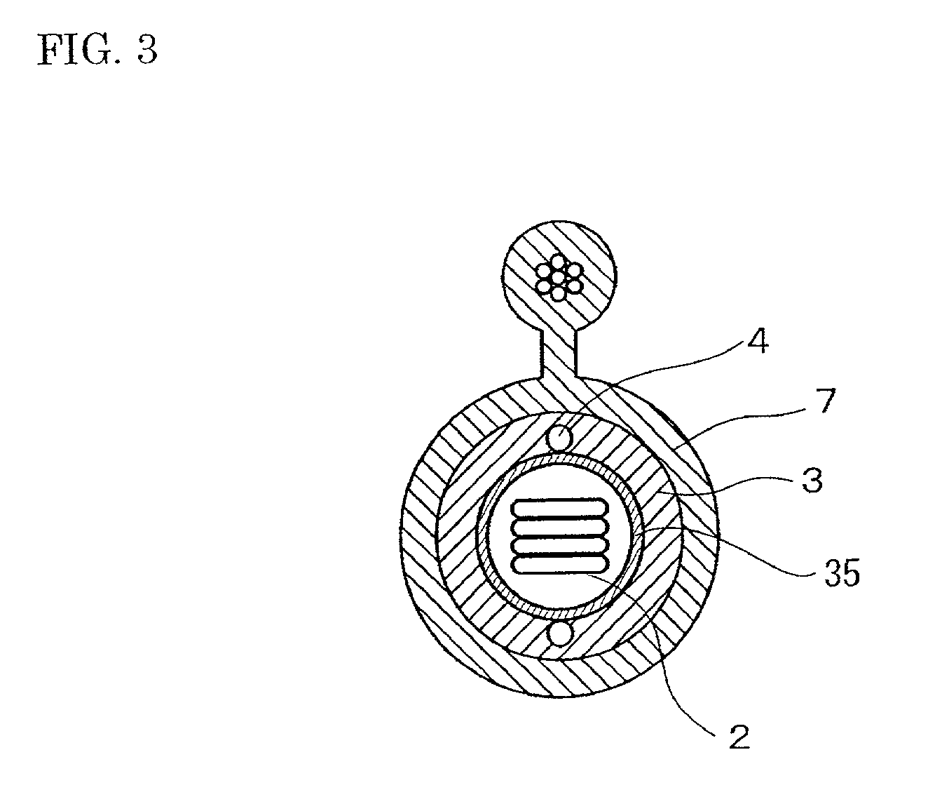
[0057] A cable core was formed by stacking four optical fiber ribbons, each of which included twelve optical fibers, and was covered by an inner cover layer formed of polyethylene. An inside diameter of the inner cover layer was 6 mm and an outside diameter thereof was 12 mm. Then, a main cable was constructed by embedding two strength members, each having a diameter of 1 mm, in the inner cover layer such that they were arranged on a plane which passed through the central axis of the inner cover layer. The distance between the strength members and the central axis of the main cable was 5 mm. Then, self-supporting cables were manufactured from the main cable and a support member, which was formed by stranding seven steel wires, each having a diameter of 2.0 mm, by using the manufacturing apparatus shown in FIGS. 4A and 4B.

[0058] A plurality of self-supporting cables were manufactured by using rollers of different diameters as the rollers 25 and 28, and the alignment accuracy of the s...


PUM


Abstract

A self-supporting cable includes a main cable constructed by covering a cable core with an inner cover layer and installing one or more strength members inside the inner cover layer such that they lie on a plane passing through the central axis thereof; a support member; and an outer cover layer formed so as to cover the main cable and the support member while they are arranged in parallel. A support member portion including the support member and a part of the outer cover layer and a main cable portion including the main cable and a part of the outer cover layer are connected by connecting portions, which are also a part of the outer cover layer, in the longitudinal direction thereof. The main cable portion is made longer than the support member portion so that there is an allowance in the length thereof.

Description

[0001] 1. Field of the Invention[0002] The present invention relates to a self-supporting cable which is installed overhead and is used as a subscriber line, and also relates to a method for manufacturing the self-supporting cable.[0003] 2. Description of the Background Art[0004] Self-supporting cables having a construction as shown in FIGS. 8A to 8C have been suggested as optical fiber cables to be installed overhead for subscriber lines in optical communications networks. FIGS. 8A and 8B show an example of such a conventional self-supporting cable, wherein FIG. 8A is a perspective view thereof and FIG. 8B is a cross-sectional view thereof. FIG. 8C is a cross-sectional view of a cable core used in the self-supporting cable. In FIGS. 8A to 8C, reference numeral 41 denotes optical fiber ribbons, 41a denotes optical fibers, 41b denotes optical fiber coatings, 41c denotes coated optical fibers, 41d denotes ribbon coatings, 42 denotes a cable core, 43 denotes a support member, 44 denote...

Claims


Application Information

Patent Timeline
IPC IPC(8): G02B6/44H01B7/18H01B11/00H01B13/00H01B13/24
CPCG02B6/4405G02B6/4484G02B6/4422
Inventor SAKABE, ITARUISHIKAWA, HIROKIAKASAKA, NOBUHIROTSURUMI, TAKEOYAMANE, YOSHIRO
Owner SUMITOMO ELECTRIC IND LTD
Why Eureka
Try Eureka