Grinding machine

a grinding machine and grinding head technology, applied in grinding drives, grinding heads, manufacturing tools, etc., can solve problems such as uneven thickness

Inactive Publication Date: 2002-06-27
DISCO CORP
View PDF5 Cites 43 Cited by
  • Summary
  • Abstract
  • Description
  • Claims
  • Application Information

AI Technical Summary

Problems solved by technology

As a result, the semiconductor wafer W was coarse-ground to

Method used


Image

  • Grinding machine
  • Grinding machine
  • Grinding machine

Examples


Embodiment Construction

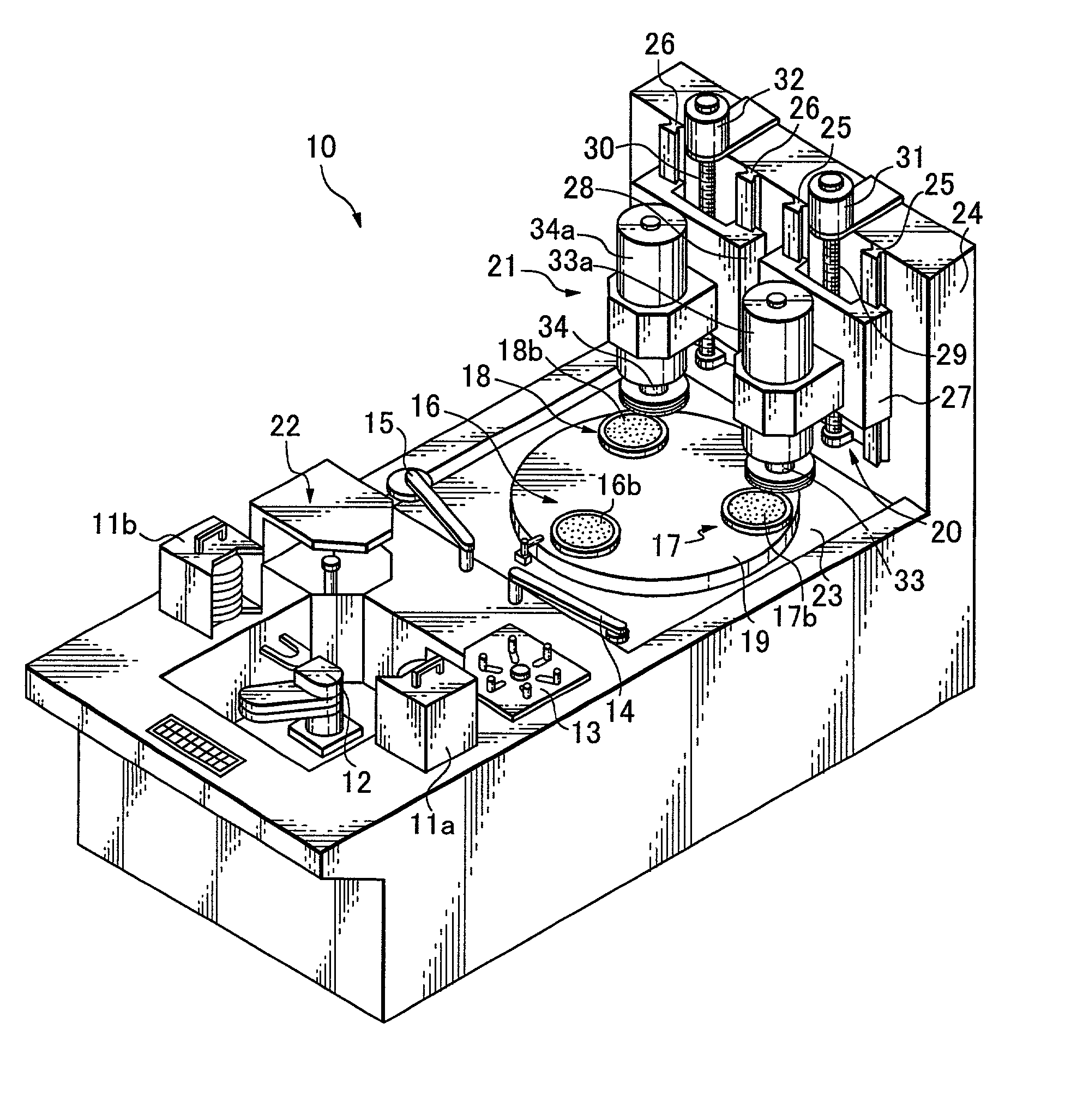
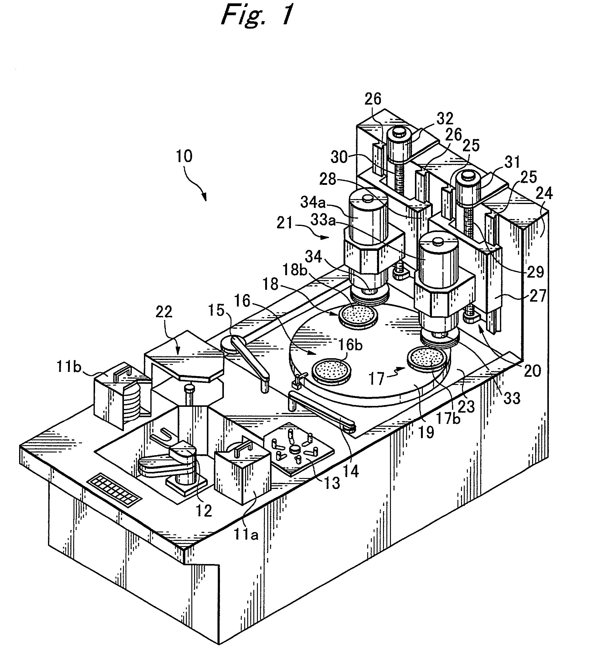
[0034] Referring to FIG. 1, a grinding machine 10 can be used in effecting first, coarse-grinding and second, fine-grinding on the rear side of a semiconductor wafer.

[0035] As shown, the grinding machine 10 comprises two cassettes 11a and 11b for containing plate-like objects such as semiconductor wafers to be ground, means 12 for taking semiconductor wafers out of the cassette 11a and putting them into the cassette 11b, a centering table 13 for putting a selected semiconductor wafer taken out from the cassette 11a in transferring position, first and second transporting means 14 and 15, chuck tables 16, 17 and 18 for sucking and holding semiconductor wafers, a turn table 19 having the chuck tables 16, 17 and 18 rotatably fixed thereto, first and second grinding means 20 and 21 for coarse- and fine-grinding semiconductor wafers, and washing means 22 for washing semiconductor wafers subsequent to grinding.

[0036] The grinding machine 10 has an upright wall 24 standing from its base 23,...


PUM


Abstract

Disclosed is an improvement in a grinding machine comprising at least a turn table, rotary chuck tables for holding work pieces to be machined, a first grinding means for grinding the work piece held on the chuck table and a second grinding means for grinding the first-ground work piece held on the chuck table. The first grinding means comprises at least a first grinding wheel having pieces of grindstone set so as to define together a first grinding plane, and a first spindle fixed to the first grinding wheel. Likewise, the second grinding means comprises a second grinding wheel having pieces of grindstone set so as to define together a second grinding plane and a second spindle fixed to the second grinding wheel. The first and second grinding means are so arranged that the first angle formed between the linear line connecting from the center of rotation of the turn table to the center of rotation of a selected chuck table and the linear line connecting from the center of rotation of the selected chuck table to the center of rotation of the first spindle is equal to the second angle formed between the linear line connecting from the center of rotation of the turn table to the center of rotation of the selected chuck table and the linear line connecting from the center of rotation of the selected chuck table to the center of rotation of the second spindle. This arrangement assures that all finished work pieces have on and same thickness.

Description

[0001] 1. Field of the Invention[0002] The present invention relates to a grinding machine for use in grinding plate-like objects such as semiconductor wafers.[0003] 2. Related Arts[0004] Referring to FIG. 7, a plate-like object such as a semiconductor wafer W is attached to a chuck table 60 with its rear side up by using a protective tape T between its front side and the top surface of the chuck table 60. The rear side of the semiconductor wafer W is ground by a grinding means 70.[0005] The grinding means 70 comprises a rotary spindle 71, a mount 72 integrally connected to the rotary spindle 71 and a grinding wheel 73 fixed to the mount 72. The annular grinding wheel 73 has pieces of grindstone 74 fixed to its lower surface, as seen from FIG. 8. While the grinding wheel 73 is made to rotate, the grinding means 70 is lowered until the pieces of grindstone 74 have been applied to the rear side of the semiconductor wafer W under pressure, thereby grinding the rear surface of the semic...

Claims


Application Information

Patent Timeline
IPC IPC(8): B24B7/04B24B7/22B24B41/047
CPCB24B7/04B24B41/047B24B7/228
Inventor MORI, TAKASHISASAYAMA, HIROSHITAKAZAWA, TORU
Owner DISCO CORP
Why Eureka
Try Eureka