In-mold label with perforations

Inactive Publication Date: 2002-09-12
MAIL WELL
View PDF0 Cites 34 Cited by
  • Summary
  • Abstract
  • Description
  • Claims
  • Application Information

AI Technical Summary

Benefits of technology

0009] The present invention provides an improved in-mold label having perforations and a method and apparatus for creating such labels. The in-mold label of the present invention substantially reduces blistering during the blow molding process. According to the present in

Problems solved by technology

Preferably, the perforations impair the aesthet

Method used


Image

  • In-mold label with perforations
  • In-mold label with perforations
  • In-mold label with perforations

Examples


Example

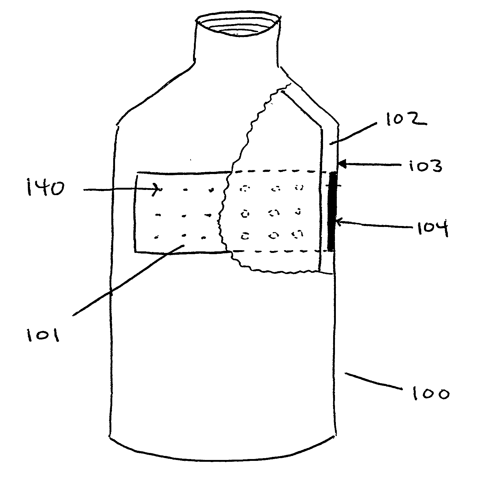
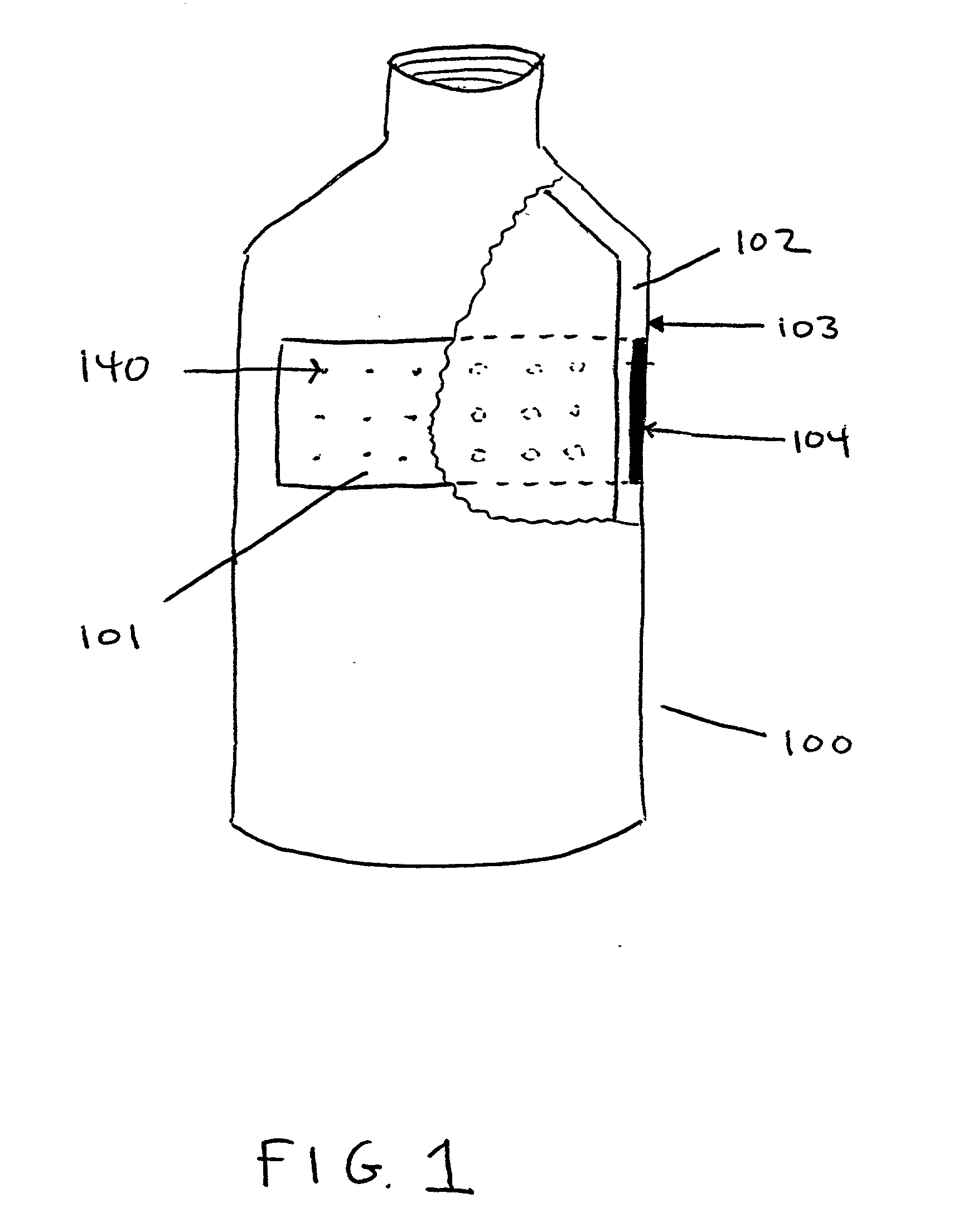
[0024] In the figures, like numerals indicate like parts. FIG. 1 is a front view of a plastic container 100 with an in-mold label 101 having perforations 140 according to the present invention. In FIG. 1, part of the in-mold label 101 and the sidewall 102 of the plastic container 100 are cut away to reveal how the in-mold label 101 is embedded within the sidewall 102 of the plastic container 100. The in-mold label 101 preferably is substantially contained within (and becomes part of) the sidewall 102 of the plastic container 100, with the outer surface 103 of the plastic container 101 nearly flush with the printed side 104 of the in-mold label 101.

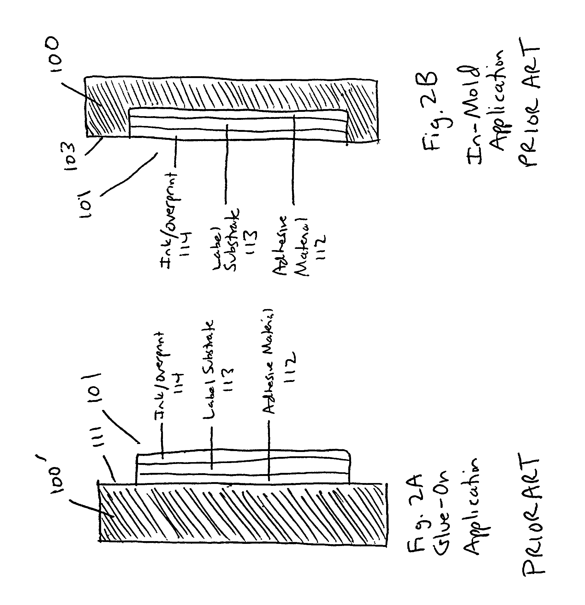
[0025] FIG. 2A depicts a side view of a label 101 that is attached with an adhesive to the outer surface 111 of a plastic container 100. FIG. 2B depicts a side view of an label 101 embedded in the plastic container 100. As shown in FIGS. 2A and 2B, the label 101 is generally comprised of three layers: the inner adhesive material layer 112;...


PUM

PropertyMeasurementUnit
Lengthaaaaaaaaaa
Diameteraaaaaaaaaa
Diameteraaaaaaaaaa

Abstract

An improved method for preparing a molded plastic container with embedded label in which the label contains one or more perforations to reduce blistering during the blow molding process. In a preferred embodiment, the perforations are larger on one side of the label than the other to facilitate the release of gases that otherwise would be trapped behind the label.

Description

[0001] This application claims priority from U.S. provisional patent application Serial No. 60 / 181,801 filed on Feb. 11, 2000.I. FIELD OF THE INVENTION[0002] This invention relates to an improved in-mold label and a method and apparatus for creating and using the same.II. BACKGROUND OF THE INVENTION[0003] In-mold labeling is a method for pre-decorating a wide variety of plastic containers by embedding labels during the blow molding process used to fabricate the containers. Blow molding is a process well-known in the art. One type of blow molding process, extrusion blow molding, starts when granulated plastic resin material is melted into a molten state. The liquid plastic is formed into a "parison," often cylindrical in shape, which is then placed between two mold halves. The mold halves come together and a blow-pin is injected into the parison. The blow-pin exerts a blow pressure that reshapes the parison to the geometric design of the mold cavity. The air in the mold surrounding t...

Claims


Application Information

Patent Timeline
IPC IPC(8): B29C49/04B29C49/24G09F3/04
CPCB29C49/04B29C49/24B29C49/2408B29C2049/2412B29C2049/2425B29C2049/2427B29C2049/2437B29C2049/2472B29K2995/005B29K2995/0053B29L2031/712G09F3/04Y10T428/24273Y10T428/24322
Inventor MUIR, RONLACHANCE, RENE
Owner MAIL WELL
Why Eureka
Try Eureka