Supercharge Your Innovation With Domain-Expert AI Agents!

Process and apparatus for casting a continuous metal strand

a technology of metal strands and processing equipment, applied in the direction of mold control devices, manufacturing tools,foundry moulding apparatus, etc., can solve the problems of series of possible errors which have an influence on the force exerted on the strand and consequently on the quality of the strand

Inactive Publication Date: 2002-12-19
MANNESMANN AG
View PDF0 Cites 4 Cited by
  • Summary
  • Abstract
  • Description
  • Claims
  • Application Information

AI Technical Summary

Problems solved by technology

In the force flux system which involves the roller over its entire length, the bearings in which the rollers are guided, the stand parts on which the bearings are supported and the tie rods which are moved mechanically or hydraulically, there are a series of possibilities for errors which have an influence on the force exerted on the strand and consequently on its quality.

Method used


Image

  • Process and apparatus for casting a continuous metal strand
  • Process and apparatus for casting a continuous metal strand
  • Process and apparatus for casting a continuous metal strand

Examples


Embodiment Construction

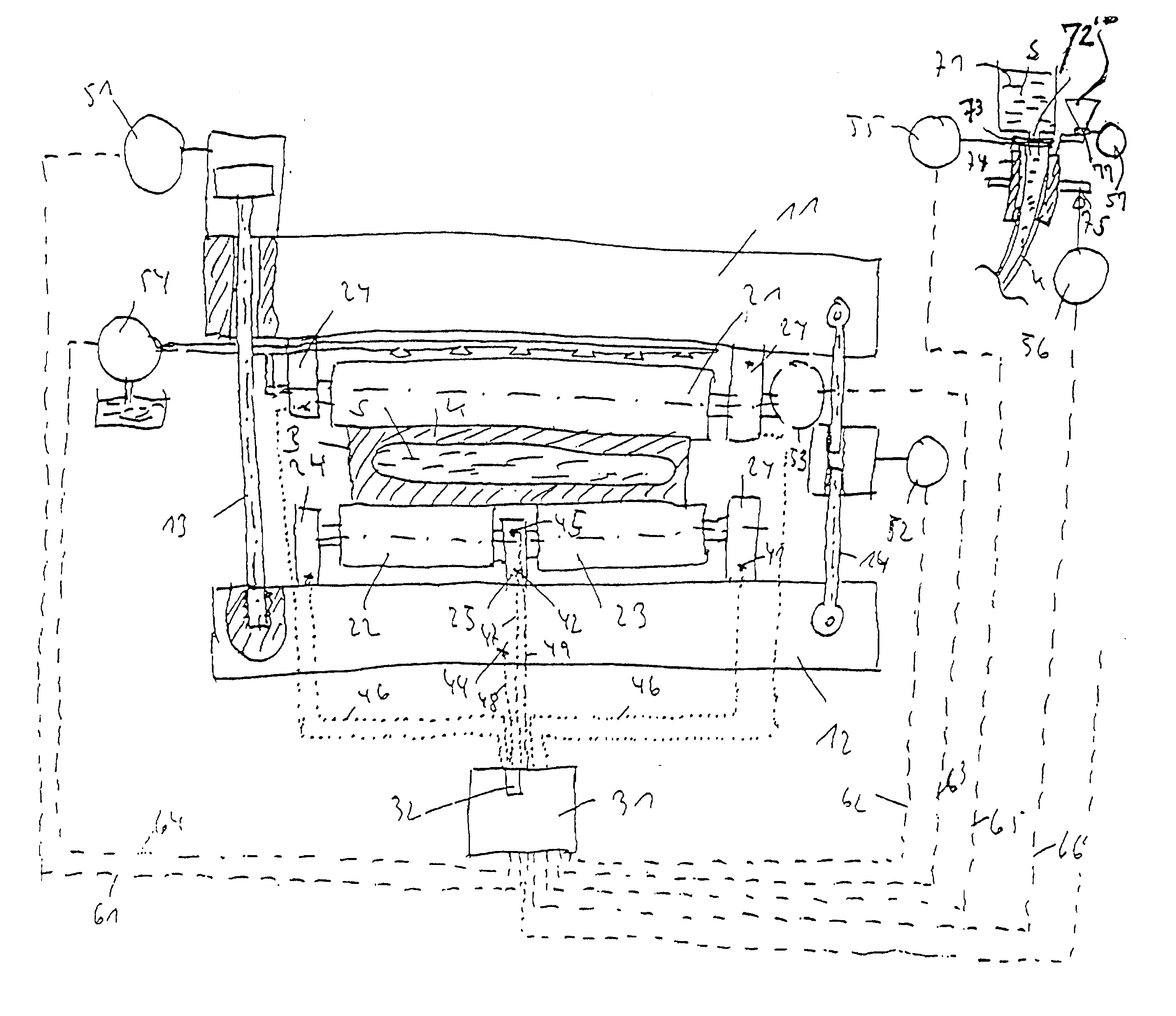
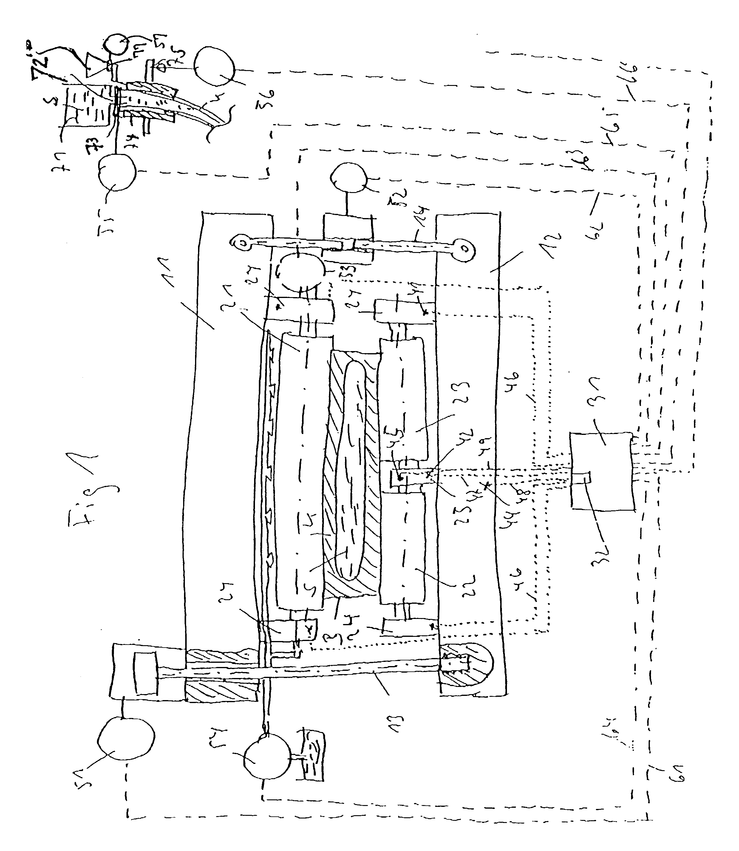
[0029] FIG. 1 shows an upper stand 11, which is connected by means of tie rods 13, 14 to a lower stand part 12. In the left-hand part of the figure, the tie rod 13 is hydraulically actuated and thus connected to an actuator 51. In the right-hand part of FIG. 1, the tie rod 14 can be mechanically actuated and is connected to an actuator 52.

[0030] The upper stand part is connected to a one-part roller 21, which is mounted in outer bearings 24.

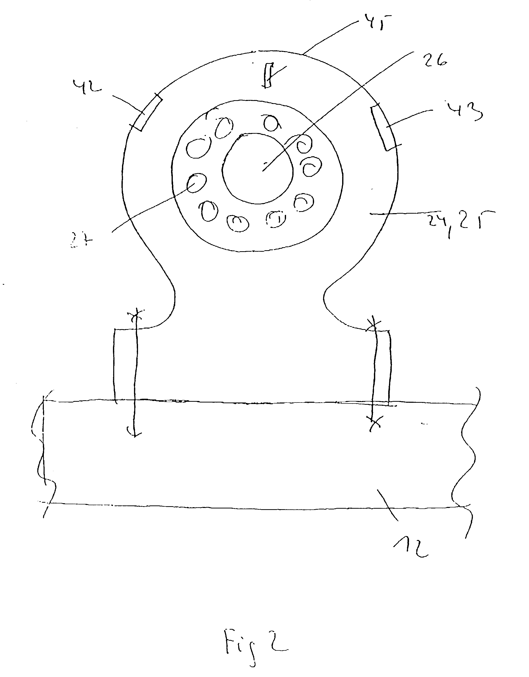
[0031] The lower stand part has a so-called split roller, having a first split roller 22 and a second split roller 23. The rollers 22, 23 are mounted in outer bearings 24 and in a central bearing 25.

[0032] Between the rollers 21 and 22, 23 there is a slab B, which has a shell casing K, which encloses the melt S.

[0033] Provided in the outer bearings 24 and in the central bearing 25 arc force-measuring elements 41 and 42, respectively, which are connected to a computing unit 31 via measuring lines 46 and 47.

[0034] Additionally provided in the centr...


PUM

PropertyMeasurementUnit
compressive forceaaaaaaaaaa
compression forceaaaaaaaaaa
temperatureaaaaaaaaaa

Abstract

An apparatus and process for casting a continuous metal strand, in particular steel, in a continuous casting apparatus having strand parts disposed opposite one another and being fitted with bearings in which guide rollers are mounted, and having actuators by which a gap between respective opposed rollers can be set infinitely variable, and which method includes sensing a value representing a compressive force which occurs in the bearings and feeding said value to a computing unit; comparing the individual measured force values of a roller or of a pair of oppositely disposed rollers with respect to a level of the force; and utilizing at least the relating highest value measured as a command variable for controlling the gap and / or the casting rate and / or the amount of cooling water and / or the melt feed and / or the casting powder feed and / or the mold oscillation.

Description

[0001] 1. Field of the Invention[0002] The present invention relates to a process and apparatus for casting a continuous metal strand, in particular of steel, in a continuous casting apparatus having stand parts disposed opposite one another and fitted with bearings in which guide rollers are mounted, and having actuators by which the gap between respective appropriately disposed rollers can be set infinitely variably.[0003] 2. Description of the Related Art[0004] During the continuous casting, for example, of rectangular formats, the gap, i.e. the clear spacing, between two rollers lying opposite one another is set to correspond to the shrinkage behavior of the strand formed into the slab or bloom over the length of the machine. In so-called soft reduction, the gap is set narrower as the shrinkage behavior of the strand proceeds, in order to achieve an improvement in the internal quality, in particular of the slab, in the area of residual solidification. Since the position of the l...

Claims


Application Information

Patent Timeline
Patent Type & Authority Applications(United States)
IPC IPC(8): B22D11/16B22D11/18B22D11/20B22D11/22
CPCB22D11/163B22D11/165B22D11/225B22D11/20B22D11/18
Inventor ASHBURN, RONALD E.
Owner MANNESMANN AG
Features
  • R&D
  • Intellectual Property
  • Life Sciences
  • Materials
  • Tech Scout
  • Unparalleled Data Quality
  • Higher Quality Content
  • 60% Fewer Hallucinations
Learn More