
Vertically stabilized adjustable shelf bracket assembly

Inactive Publication Date: 2003-01-09
HERRON INTPROP HLDG L L C
View PDF0 Cites 28 Cited by
  • Summary
  • Abstract
  • Description
  • Claims
  • Application Information

AI Technical Summary

Benefits of technology

[0006] It is an object of the invention to provide a shelf bracket assembly in which the shelves are substantially stable.
[0008] It is another object of the invention to provide a shelf bracket assembly in which the shelves may be easily adjusted.
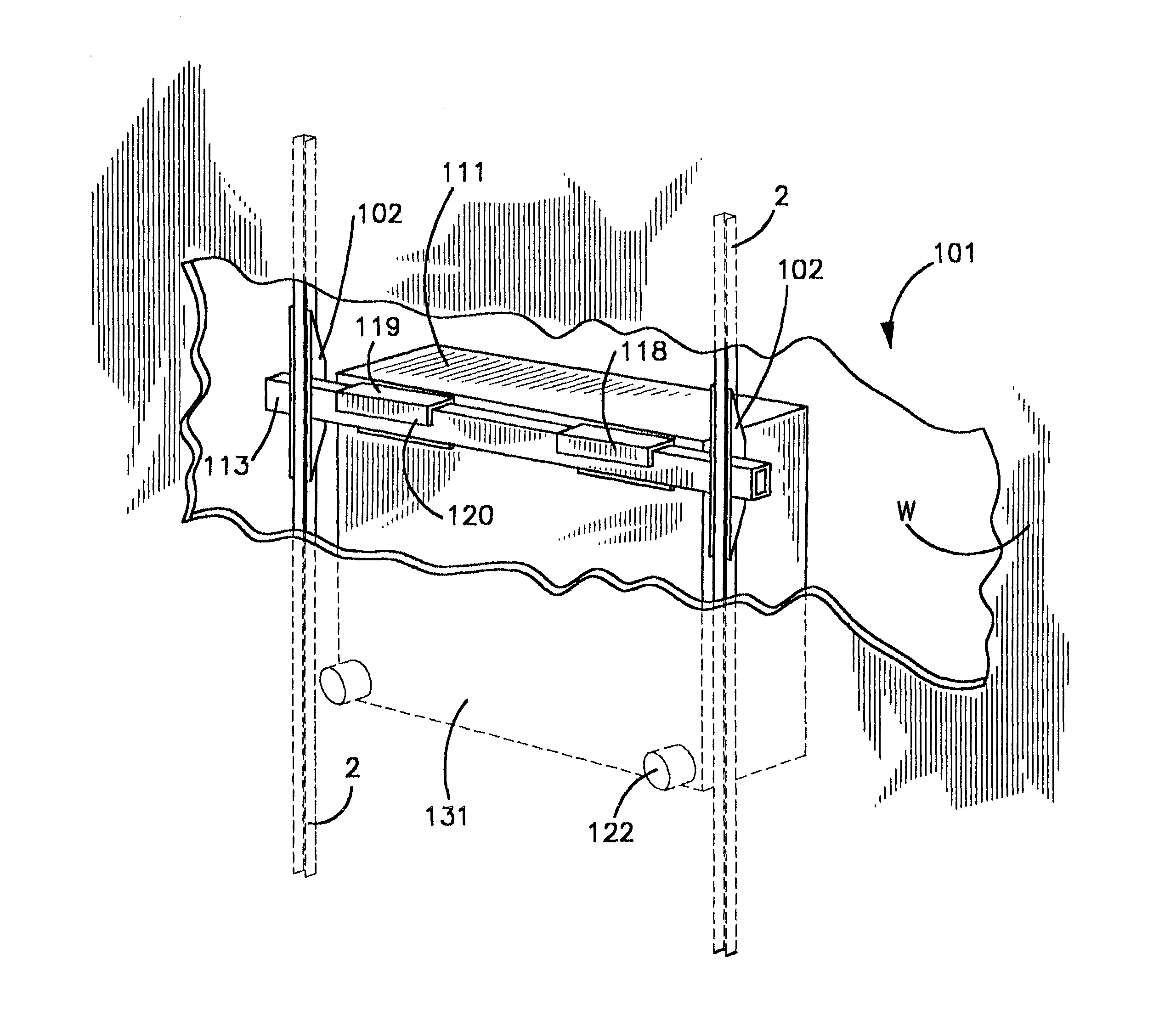
[0010] A shelf bracket assembly is disclosed for providing improved vertical stability to adjustable shelves. The assembly comprises a plurality of Gartung type support strips, containing a plurality of vertically aligned slots along their length. A plurality of shelf brackets having a base and a horizontal support member extending from the base are provided. The base contains at least one hooked portion sized to fit in and engage the vertically aligned slots of the support strips. The shelves are stabilized vertically in several ways. First the base is provided with a recess for receiving the shelf. The shelf is either sized to fit securely in the recess or the recess is provided with a shim to secure the shelf in the recess. Second, a vertical member may extend upwardly from the horizontal support member, preferably at the end of the horizontal support member opposite the base. A slot or an indentation may be provided in the shelf to receive the vertical member. The slot or indentation and the vertical member are preferably configured to engage one another so that the shelf is releasably attached to the horizontal member. This may be accomplished by providing the vertical member with an enlarged head and providing the slot or indentation with a deformable constriction sized to engage the head. With the shelf attached to the horizontal support member at one end by the vertical member and at the other end in the recess, the shelf is secured to the horizontal support member so that it cannot pivot vertically along its width. Securing the shelf to another horizontal support member attached to a parallel support strip will provide additional vertical stability along the shelf length. In this position, the shelf can be displaced vertically only by moving the entire support bracket upward, as would be done to remove the bracket from the support strip.

Problems solved by technology

For this reason, small lateral forces can cause the brackets and the shelves they support to sway substantially.
Gartung type shelving system also have vertical stability problems.
This can create problems if the shelf becomes unevenly laden.
Lifting the sculpture during household cleaning may cause the shelf to become unbalanced and allow it to pivot on the bracket, and may lead to a tumble for the lamps.
The shelves are also quite susceptible to displacement from upward forces.
If the bracket itself is bumped from below, it may be displaced and possibly even knocked out of the strip.
Previous works, such as U.S. Pat. No. 5,253,835 to Herron which is hereby incorporated by reference in its entirety, have made substantial improvements to the horizontal stability of the shelving; however, problems persist in the state of the art with respect to the vertical stability of Gartung type shelving.

Method used


Image

  • Vertically stabilized adjustable shelf bracket assembly
  • Vertically stabilized adjustable shelf bracket assembly
  • Vertically stabilized adjustable shelf bracket assembly

Examples


Embodiment Construction

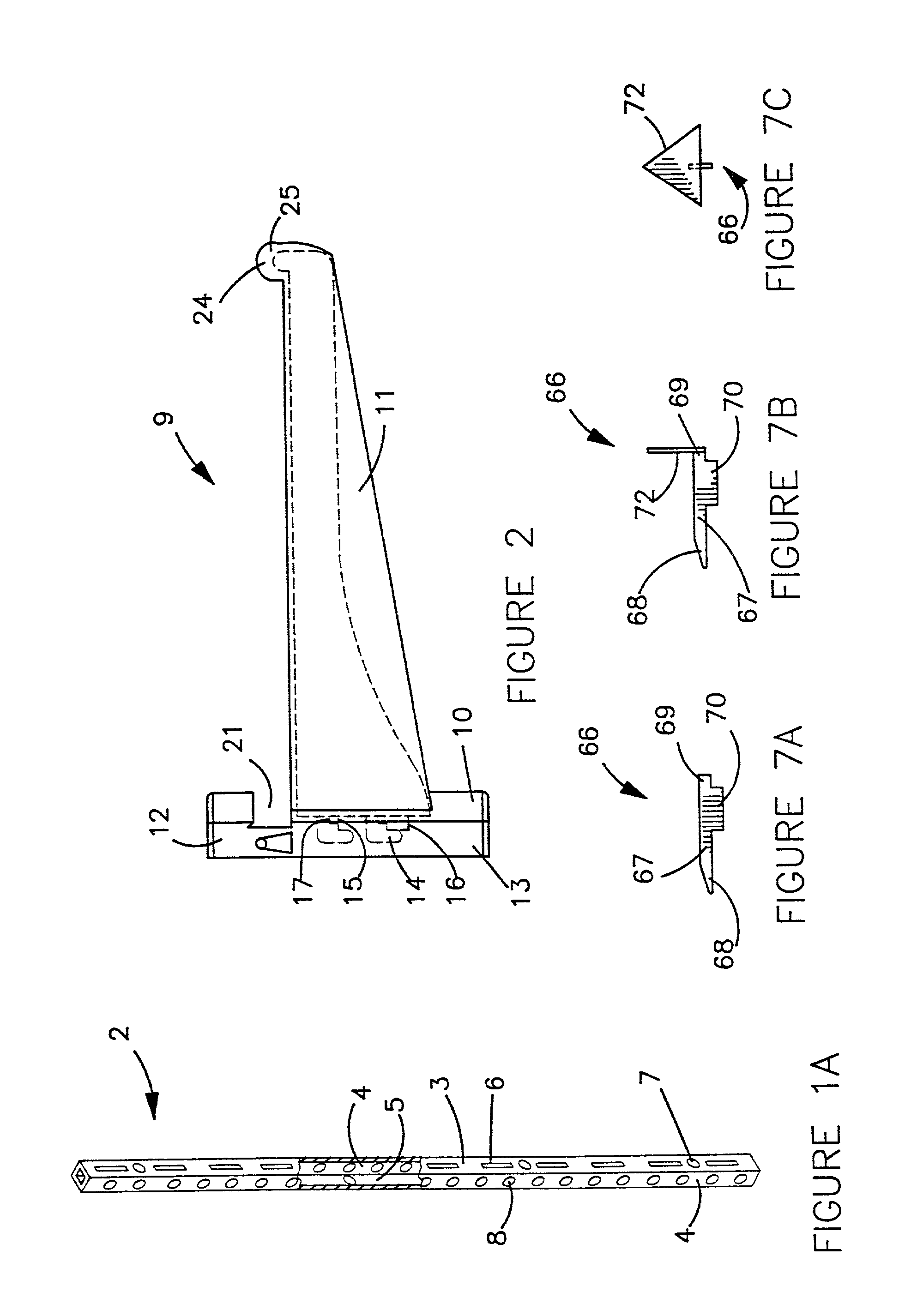
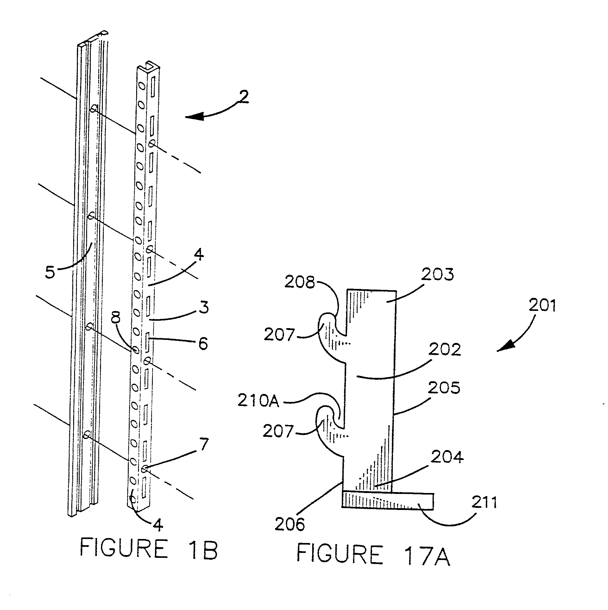
[0059] A shelf bracket assembly 1 is disclosed. Shelf bracket assembly 1 comprises a plurality of vertical support strips 2. Support strips 2 are preferably provided with a face 3 and generally perpendicular sidewalls 4. For added strength, support strips 2 may also be provided with a back wall 5, opposite face 3. In one preferred embodiment, back wall 5 may be provided as separate piece from the rest of support strip 2, as illustrated in FIG. 1B. When this embodiment is used, back wall 5 preferably contains a pair of aligned grooves sized to receive the edges of sidewalls 4. Support strip 2 preferably contains a plurality of slots 6 in face 3. Slots 6 should be evenly spaced and vertically aligned. In one preferred embodiment (not shown) two parallel columns of slots 6 are provided in strips 2. When this embodiment is used, two columns of hook members 14 (described below) may be provided on shelf bracket 9 (also described below). Support strips 2 are also preferably provided with a...


PUM


Abstract

A vertically stabilized shelf bracket assembly having at least two support strips on which a plurality of shelf brackets are mounted. The shelving is stabilized in several ways. First, the brackets are provided with a shelf engaging recess. The recess is either designed to provide a tight fit for the shelf, or the recess is provided with a shim for tightening the fit. Second, the brackets are provided with a vertical member which engages the shelves. Preferably, the recess and the vertical member will engage the shelf at opposite ends of the shelf, securing the shelf to the bracket. When the shelf is attached to multiple brackets, the shelf will be prevented from pivoting on the bracket. The shelves can be further stabilized by securing the brackets against vertical displacement. This can be accomplished by securing the shelf brackets to the support strip with a locking pin. With the locking pin in place, the shelf bracket cannot be moved upward. Another way of securing the brackets is to provide a vertical stabilizer, comprising an elongated member, preferably of steel or aluminum, having an arm extending perpendicularly therefrom. The arm will fit tightly into a slot in a support strip. When the arm is in place, the elongated member will be positioned over and in contact with the base of the shelf bracket, so that the bracket cannot be moved upward. The vertical stabilizer will be held in place by the cover which fits over the support strips.

Description

CONTINUATION-IN-PART INFORMATION[0001] This is a Continuation-in-Part of U.S. patent application Ser. No. 09 / 255,258, which will issue as U.S. Pat. No. 6,196,141 on Mar. 6, 2001, and which is hereby incorporated by reference, in its entirety.[0002] 1. Field of the Invention[0003] The invention relates to adjustable shelf support systems in general, and more particularly to shelf support systems employing slotted shelf support strips.[0004] 2. Prior Art[0005] A common adjustable shelving design in the prior art utilizes a design disclosed in U.S. Pat. No. 4,070,803 to Gartung, which is hereby incorporated by reference. This shelving system consists essentially of two or more vertical support strips containing a plurality of vertically aligned slots. Shelf support brackets having hooks designed to engage the slots in the support strips are attached to the strips. By positioning two or more strips parallel to each other on a wall, and aligning two or more brackets horizontally on the s...

Claims


Application Information

Patent Timeline
IPC IPC(8): A47B57/42A47B95/00A47B96/00A47B96/02A47B96/06
CPCA47B57/42A47B95/008A47B96/00A47B96/028A47B96/061
Inventor HERRON, WARREN L. IIIHERRON, WARREN L. JR.
Owner HERRON INTPROP HLDG L L C
Learn More