Method and apparatus for timing rotors in a rotary lobe pump

a technology of rotary lobe pumps and timing rotors, which is applied in the direction of rod connections, machines/engines, liquid fuel engines, etc., can solve the problems of over-clearance, transient torque spikes to be applied between the two rotors or between the rotors, and exceed the friction limits of clamping devices

Inactive Publication Date: 2003-03-27
SPX CORP +1
View PDF0 Cites 2 Cited by
  • Summary
  • Abstract
  • Description
  • Claims
  • Application Information

AI Technical Summary

Problems solved by technology

Tight, uniform tolerances between the lobes of the two rotors and between the rotor tips and the walls of the pumping chamber are desirable because insufficient clearance results in binding and wear, while excessive clearance reduces pumping efficiency.
If the shim test fails, the typical previous design of pump must be removed from the system, taken to a shop, and overhauled.
Such obstructions can cause transient torque spikes to be applied between the two rotors or between the rotors and their driving mechanisms.
This in turn can exceed the friction limits of the clamping devices, resulting in alignment shift.
Unless the shift causes noticeable anomalies--noise, slowing of drive motors, and the like--such errors ordinarily remain in the system until the next periodic servicing event.

Method used


Image

  • Method and apparatus for timing rotors in a rotary lobe pump
  • Method and apparatus for timing rotors in a rotary lobe pump
  • Method and apparatus for timing rotors in a rotary lobe pump

Examples


Embodiment Construction

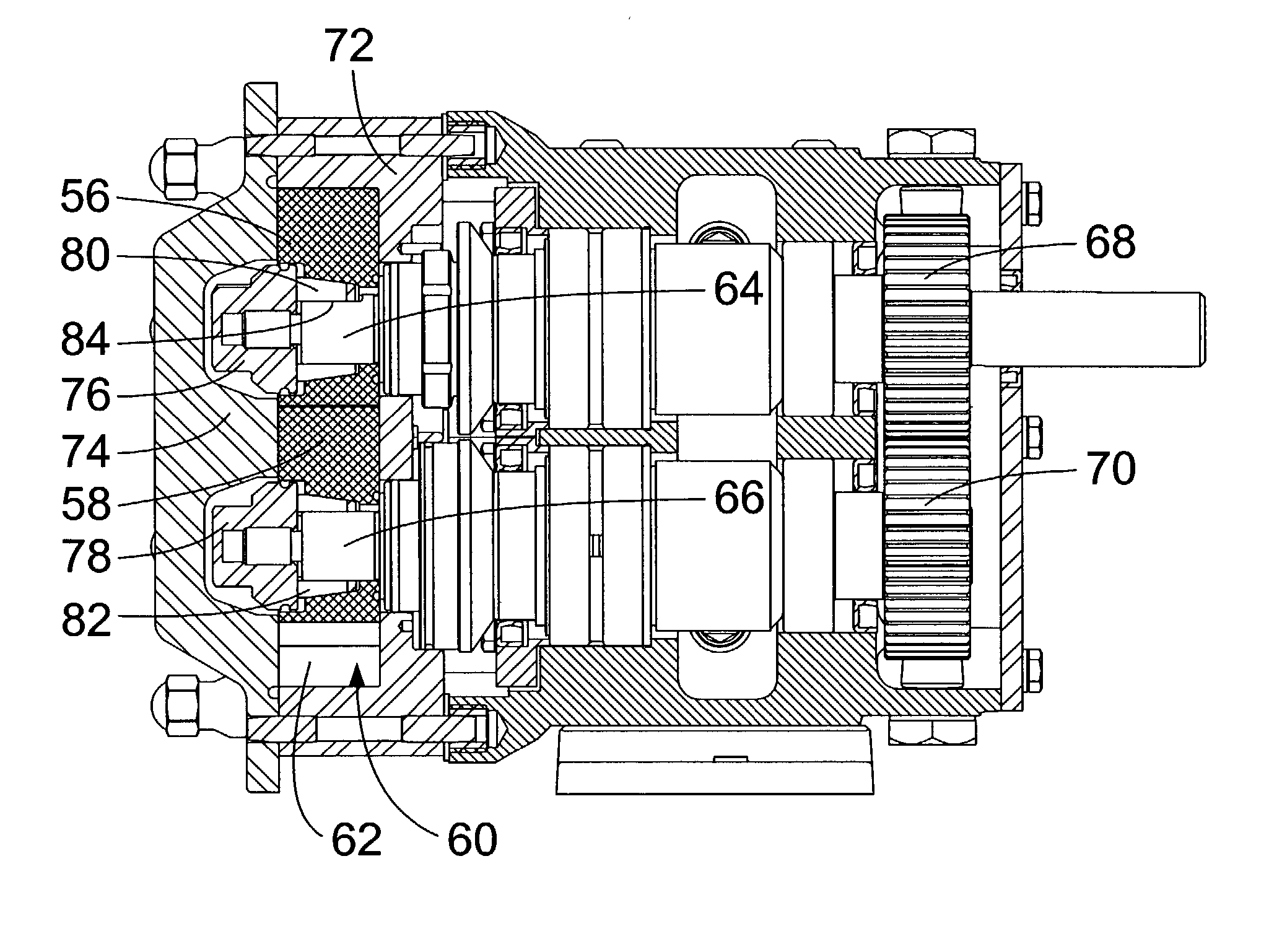
[0024] The invention provides a novel rotor attachment technique that can retain full mechanical strength in all parts of the pump, provide unimpaired ability to adjust spacing between the rotors, and leave the drive end of the pump untouched during timing adjustment. Embodiments of the invention accomplish this by keying or otherwise rigidly attaching the gears to the drive ends of the two shafts and using tapered-bushing clamping of the rotors onto their respective shafts.

[0025] A preferred embodiment of the present invention provides a slotted, tapered bushing mated to a tapered hole that comprises the center hole in a lobed rotor. These two items are placed on a shaft that has a shoulder against which the rotor rests; a keying feature, such as a flat, that aligns the bushing; and a threaded end beyond the keying feature. When the bushing is drawn into the tapered hole in the rotor by a nut riding on the threaded portion of the shaft, the rotor is stopped by the shaft shoulder, a...


PUM


Abstract

A rotary lobe pump includes two geared-together, counter-rotating shafts, to which are affixed rotors with interdigital lobes. Adjustment of the angular relationship of the rotors uses a clamping device within each rotor. The clamping device consists of a tapered, slotted bushing that is forced between a mating taper on the rotor and a locking device on the shaft by means of a flanged fastener mated to each pump shaft's threads.

Description

PRIORITY OF INVENTION[0001] The application claims priority to U.S. Provisional Patent Application Serial No. 60 / 324,525 filed Sep. 26, 2001, the disclosure of which is hereby incorporated by reference.[0002] The present invention relates generally to rotary lobe pumps. More particularly, the present invention relates to rotary lobe pump timing adjustment.[0003] Rotary lobe pumps are used in industry for positive-displacement pumping of foodstuffs, pharmaceuticals, and other materials requiring avoidance of cross-contamination, freedom from chemical interaction with a wide range of substances, and good mechanical strength. Dimensional tolerances in all parts of the pumps, especially in the vicinity of the working lobes, are extremely close. Tight, uniform tolerances between the lobes of the two rotors and between the rotor tips and the walls of the pumping chamber are desirable because insufficient clearance results in binding and wear, while excessive clearance reduces pumping effi...

Claims


Application Information

Patent Timeline
Patent Type & Authority Applications(United States)
IPC IPC(8): F04C2/12F04C15/00
CPCF04C2/126F04C15/0076Y10T403/7058F05C2201/046Y10T403/7056F04C2230/60
Inventor NORMAN, DREW VANHAGEN, CURT
Owner SPX CORP
Why Eureka
Try Eureka