
Precision guided extended range artillery projectile tactical base

a projectile base and extended range technology, applied in the field of projectiles, can solve the problems of dynamic depressurization load, rapid depressurization and dynamic depressurization load, and is difficult to achieve in the majority of systems

Inactive Publication Date: 2003-04-17
RAYTHEON CO
View PDF0 Cites 30 Cited by
  • Summary
  • Abstract
  • Description
  • Claims
  • Application Information

AI Technical Summary

Problems solved by technology

The severe environment also includes a muzzle exit event on the projectile structure, which results in rapid depressurization and dynamic depressurization loads.
This is a significant design requirement, which is difficult to achieve for most systems.

Method used


Image

  • Precision guided extended range artillery projectile tactical base
  • Precision guided extended range artillery projectile tactical base
  • Precision guided extended range artillery projectile tactical base

Examples


Embodiment Construction

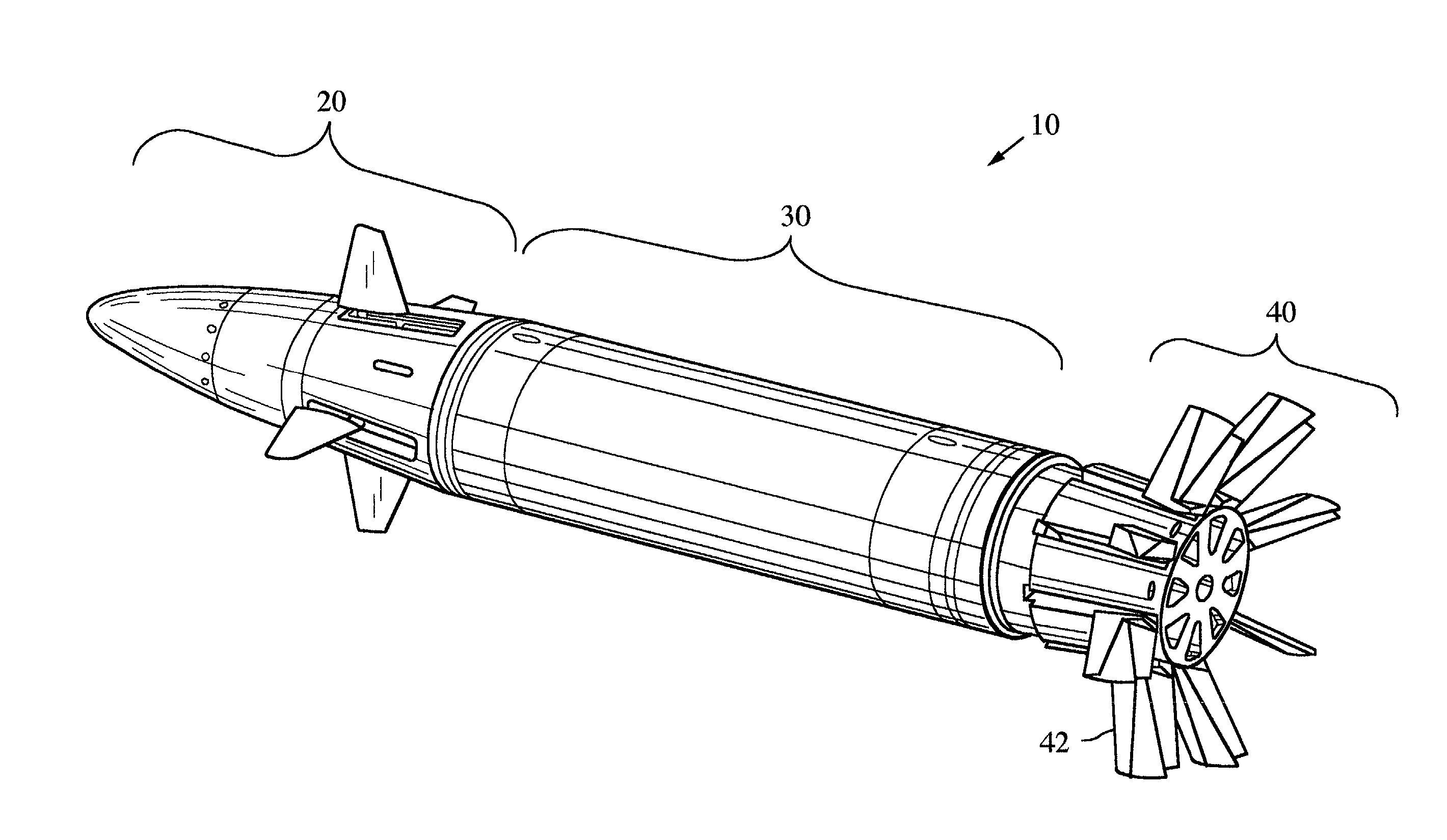
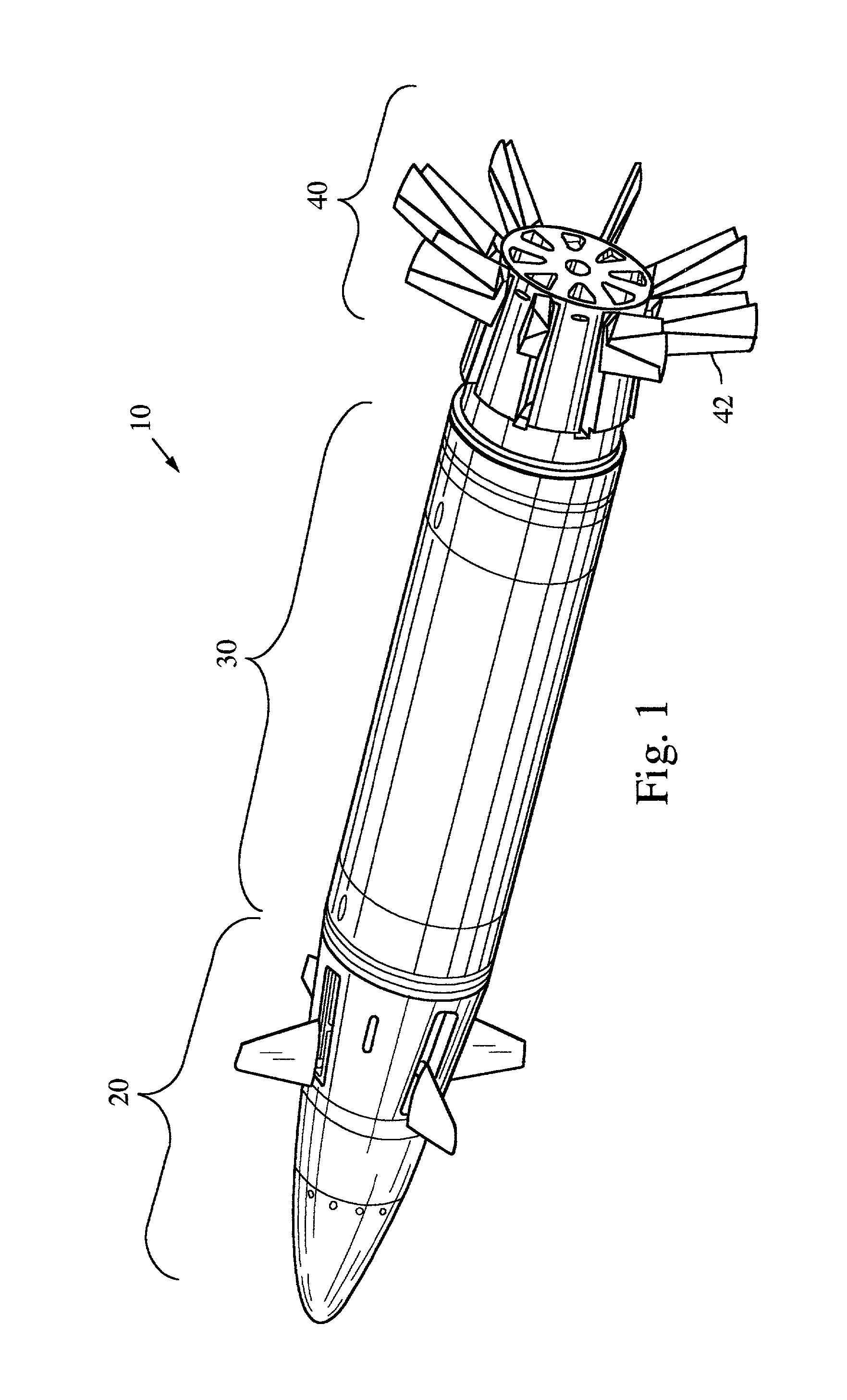
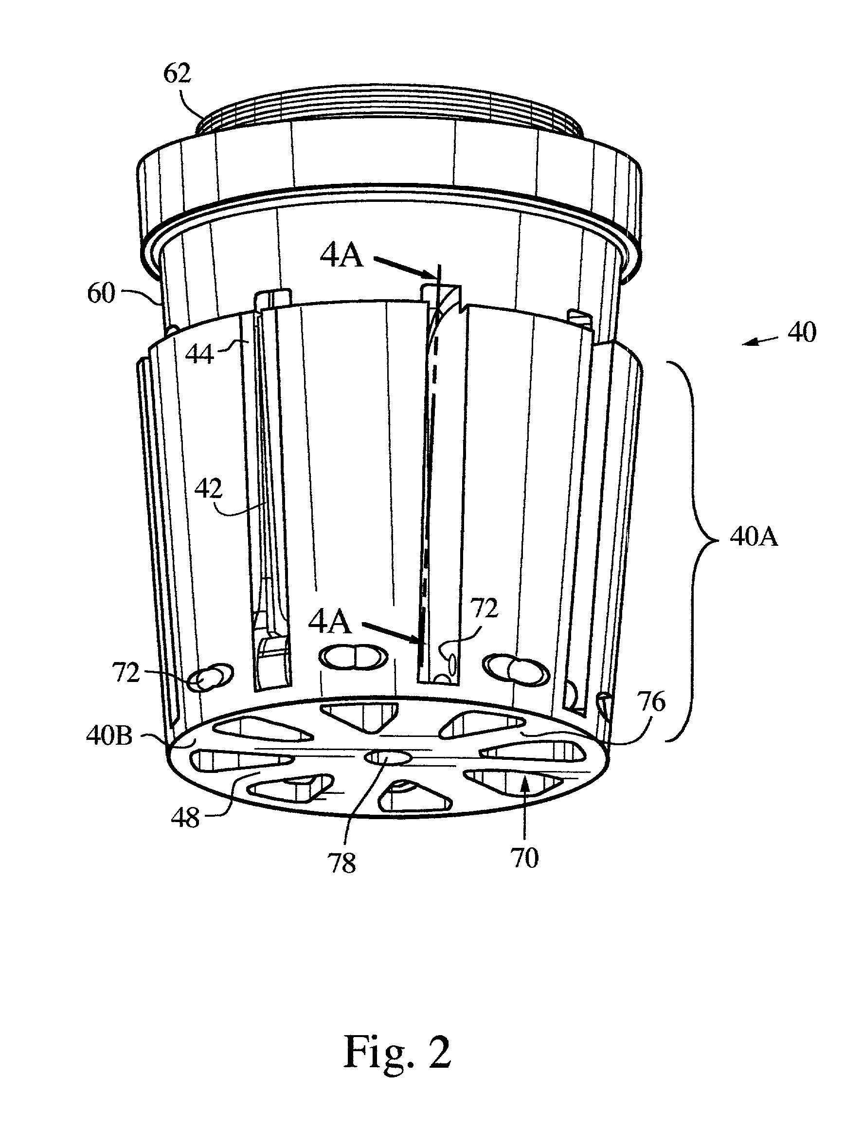
[0013] The aft most component of a guided projectile, referred to as the base, performs an important role in the success of a weapon system. The base provides the interface between the extreme pressures and shock loads resulting from the explosion of the propellant charge in the gun and the rest of the projectile. In addition, the base supports aerodynamic fins, which slow the rotation of the projectile as well as providing stabilization and lift. The fins remain stowed during the firing and deploy after the projectile exits the gun barrel and muzzle brake. The base also supports a projectile obturator, which is a device which seals the gap between the gun barrel bore and the projectile body. It maximizes the efficiency of the propellant charge impulse forces, and also rotates relative to the projectile to reduce the spin rate imposed on the projectile by the gun rifling.

[0014] The invention is applicable to guided projectile systems of various size and performance requirements. The...


PUM


Abstract

A tactical base for a guided projectile includes a base structure, and an adaptor structure for securing the base structure to a forward section of the projectile. The base further includes a plurality of fin slots, with a plurality of insert structures fitted into corresponding ones of the fin slots. A plurality of deployable fins are pivotally mounted to the base structure and supported within the insert structures for movement between a stowed position and a deployed position.

Description

TECHNICAL FIELD OF THE DISCLOSURE[0001] This disclosure is directed to projectiles such as used in artillery, and more particularly to interfaces between the explosive payload and the propelling charge.BACKGROUND OF THE DISCLOSURE[0002] Projectiles for artillery systems must survive an extremely severe environment during launch. This includes high pressure, shock waves and extreme accelerations from the initial explosion of the propellant charge. The severe environment also includes a muzzle exit event on the projectile structure, which results in rapid depressurization and dynamic depressurization loads. The gun used to launch the projectile typically has a muzzle brake, requiring any fins to clear the brake before deploying. This is a significant design requirement, which is difficult to achieve for most systems.SUMMARY OF THE DISCLOSURE[0003] A tactical base for a guided projectile is described, and includes a base structure, and an adaptor structure for securing the base structu...

Claims


Application Information

Patent Timeline
Patent Type & Authority Applications(United States)
IPC IPC(8): F42B10/14F42B10/38
CPCF42B10/38F42B10/14
Inventor MOORE, JAMES L.JOHNSON, GARY H.PETERSON, WILLIAM S.SHAH, RAJESH H.DRYER, RICHARDQUORTRUP, CONLEE O.
Owner RAYTHEON CO
Learn More