System and method to automatically extinguish a candle

a technology of automatic extinguishing and candle snuffing, which is applied in the direction of capillary burners, lighting and heating apparatuses, combustion types, etc., can solve the problems of increasing the potential for death and still fires starting

Inactive Publication Date: 2003-07-17
THE CANDLEWATCH
View PDF18 Cites 27 Cited by
  • Summary
  • Abstract
  • Description
  • Claims
  • Application Information

AI Technical Summary

Problems solved by technology

Unfortunately, one common feature of all candles is that when left unattended for too long a period of time or disturbed they can cause fires.
The worst cases are when these fires are in apartment houses or social houses since there is an even larger potential for damage to property, and even worse, an increased potential for death.
Although this solution has been moderately successful in some ways, there are still fires starting because of unattended or forgotten candles being in these containers or when these candles are disturbed in some fashion.

Method used


Image

  • System and method to automatically extinguish a candle
  • System and method to automatically extinguish a candle
  • System and method to automatically extinguish a candle

Examples


first embodiment

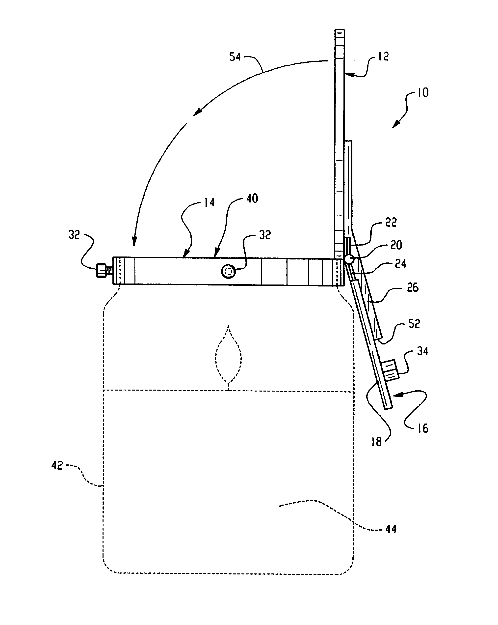
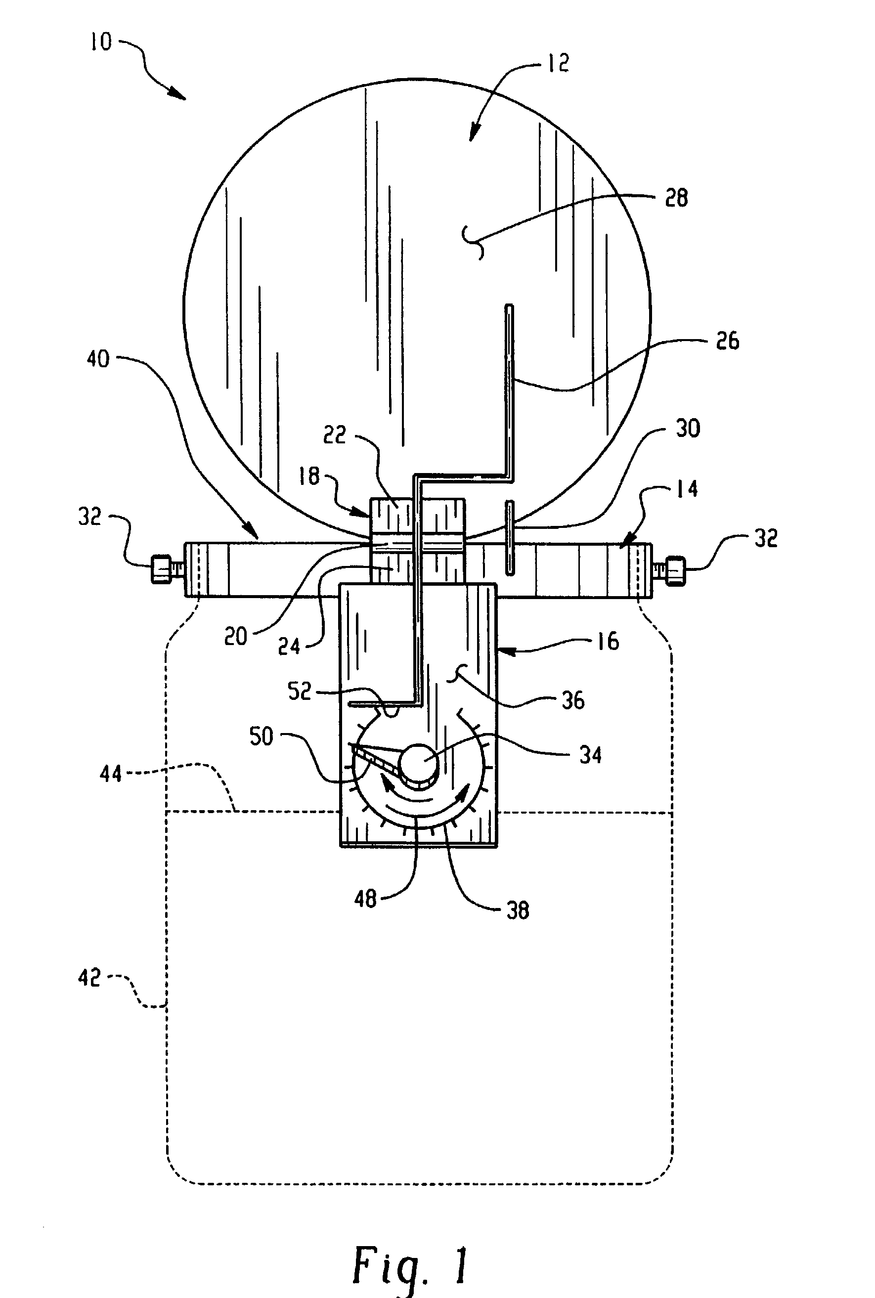
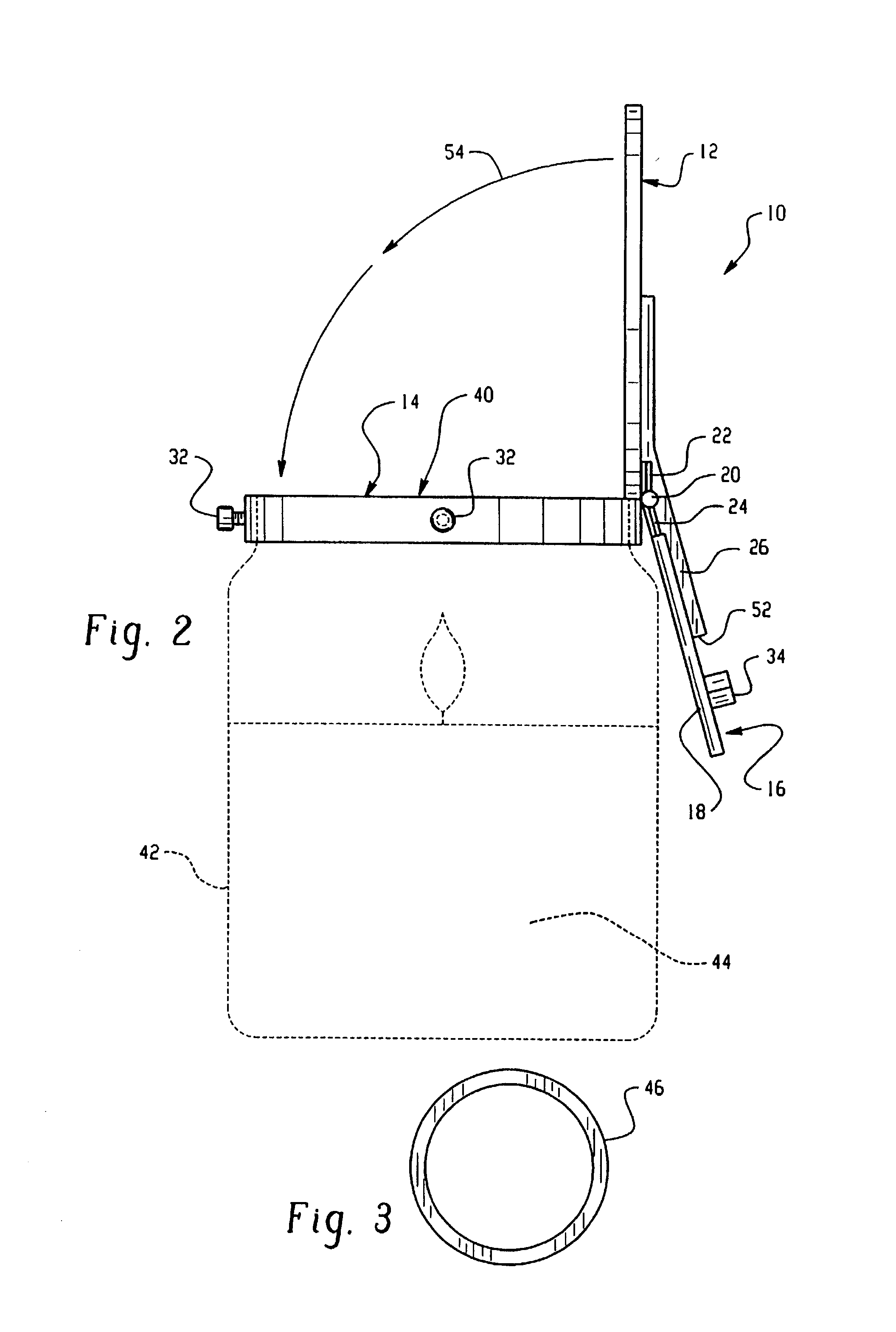
[0024] As seen in FIG. 1, an apparatus 10 according to the present invention is shown. Preferably, the apparatus 10 is a safety device for candles. The apparatus includes a first section 12, a second section 14, and a third section 16. Preferably, the first section 12 is a closing device, e.g., a lid, the second section 14 is an attachment device, e.g., a rim device or ring device, and the third section 16 is a holding device. The apparatus 10 further comprises a coupler 18 that is configured to operatively couple the first through third sections 12-16, respectively, so that the first through third sections 12-16, respectively, move relative to one another. Preferably, the coupler 18 is a hinge or flexible type device. In a preferred configuration, the center portion 20 of the coupler 18 is coupled to the second section 14, a first end portion 22 of the coupler 18 is coupled to the first section 12, and a second end portion 24 of the coupler 18 is coupled to the third section 16.

[00...

second embodiment

[0030] Turing now to FIG. 4, an apparatus 100 according to the present invention is shown. Throughout the description of FIG. 4, all elements similar to the apparatus 10 in FIGS. 1-2 will have similar elements numbers with a 100 prefix. For example, apparatus 100 in FIG. 4 for apparatus 10 in FIGS. 1-2, first section 112 in FIG. 4 for first section 12 in FIGS. 1-2. These similar elements function similarly to the elements in the previous description, so the description will not be repeated for convenience.

[0031] A main difference in the second embodiment shown in FIG. 4 is the shape and interaction of an extension 200 coupled to and extending from a surface 128 of a first section 112 and the addition of a holding device 202 that holds the extension 200 when the first section 112 is in the second position. In this embodiment, the holding device 202 pivots around pivot securing device 204. Thus, in operation an end portion 150 of a timing device 134 will interact with an end portion 2...

third embodiment

[0035] FIG. 6 is a perspective view of a system 600 according to the present invention. System 600 includes an apparatus 602. Apparatus 602 includes a closing portion 604 hingedly coupled via coupling device 606 to an attachment portion 608 and a system 610. Attachment portion 608 is releaseably secured, via any one of the securing systems discussed above or otherwise known in the art, to container 612. System 610 can be used to automatically extinguish a candle, and can include a support rod 618 and a timing device 614 having a gripping device 616. Further details of system 610 according to an embodiment of the present invention are described below with reference to FIGS. 7-8. It is to be appreciated, other configurations can be used for system 610.

[0036] FIG. 7 shows apparatus 602 with a section removed so that details of apparatus 602 when closing portion 604 is in a closed state can be seen. FIG. 8 shows system 610 with a section removed so that details of apparatus 602 when clo...


PUM


Abstract

A system and method provide a container holding a candle, a covering portion that can cover an opening of the container holding the candle, a device that automatically extinguishes the candle utilizing the covering portion and an attachment portion shaped to fit around the opening of the container holding the candle. The attachment portion can be removeably secured to the container via a securing system. The attachment portion can also be coupled to the covering portion and the device that automatically extinguishes the candle.

Description

[0001] This application is a continuation-in-part of U.S. application Ser. No. 09 / 758,933, filed Jan. 11, 2001 (to be U.S. Pat. No. 6,494,708), which is incorporated by reference herein in its entirety.[0002] 1. Field of the Invention[0003] This invention is directed towards safety devices for candles. More particularly, the invention relates to a method and apparatus for automatically actuating candle snuffers and extinguishers.[0004] 2. Background Art[0005] One of the hottest selling products in today's market are candles. These candles come in all shapes, sizes, colors, scents, and containers. Increasingly, candles are being used to set atmosphere, light rooms, change the smell of a room with fragrances, or the like. Unfortunately, one common feature of all candles is that when left unattended for too long a period of time or disturbed they can cause fires. Recently, there has been a real increase in the frequency, severity, and reporting of fires. The worst cases are when these ...

Claims


Application Information

Patent Timeline
Patent Type & Authority Applications(United States)
IPC IPC(8): F21V35/00F23Q25/00
CPCF23Q25/00F21V35/00
Inventor HART, JOHN G.RUCKER, RICHARD N.
Owner THE CANDLEWATCH
Why Eureka
Try Eureka