Seat framework for bus

a seat framework and bus technology, applied in the field of seat frameworks, can solve the problems of time-consuming and troublesome assembly of seat frameworks

Inactive Publication Date: 2003-07-31
TACHI S CO LTD
View PDF7 Cites 17 Cited by
  • Summary
  • Abstract
  • Description
  • Claims
  • Application Information

AI Technical Summary

Problems solved by technology

However, the above-described conventional bus seat framework has been found defective in requiring a number of separate reinforcing elements, such as the bracket (7) and rectangular reinforcement member (8), which means that the assembly of the seat framework is time-consuming and troublesome.

Method used


Image

  • Seat framework for bus
  • Seat framework for bus
  • Seat framework for bus

Examples


Embodiment Construction

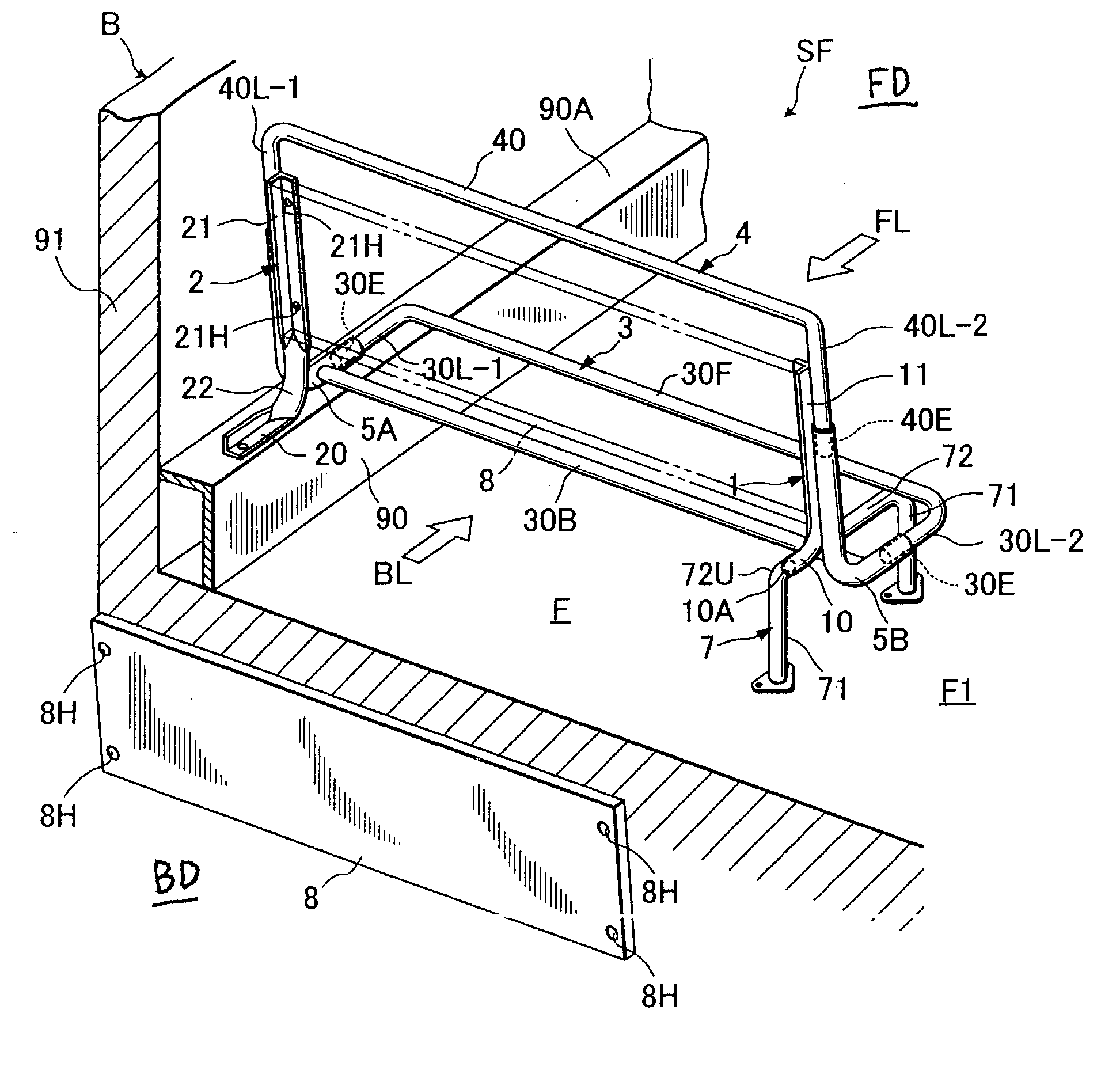
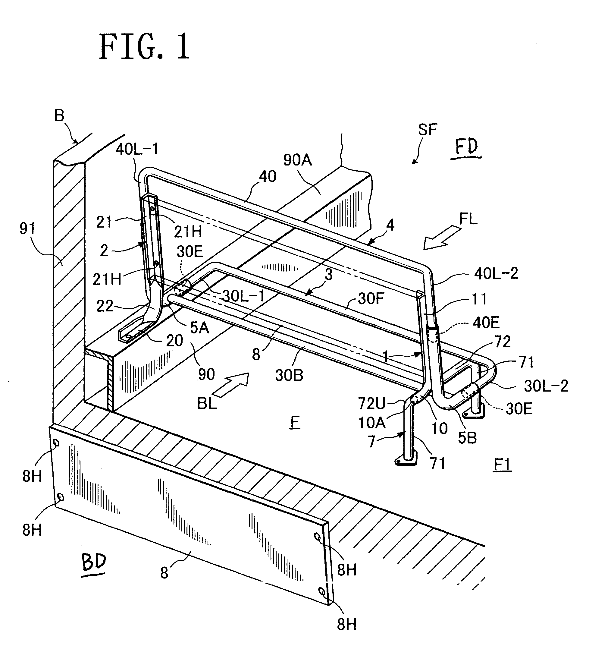
[0027] Referring to FIGS. 1 to 4, there is illustrated an exemplary preferred embodiment of seat framework for use in or adapted to be provided in a bus seat, as generally designated by (SF), in accordance with the present invention.

[0028] The illustrated seat framework (SF) is basically comprised of a tubular seat back frame member (4); a tubular seat cushion frame member (3); and a tubular support leg member (7) provided as typical one mode of support leg means for supporting those two frame members (4) (3).

[0029] As seen from FIG. 1, the seat framework (SF) is provided in a bus (B). The bus (B) has a floor (F) and a window-side wall (91). In the present embodiment, a support member (90) (formed from a rigid metallic material) is provided as another preferred mode of support leg means and disposed at the boundary corner area between the floor (F) and window-side wall (91), extending upwardly from the floor (F) to a predetermined level. The illustrated support member (90) is not li...


PUM


Abstract

A seat framework for use in a bus, which is basically from by a tubular seat back frame member and a tubular seat cushion frame member. The seat framework is fixed via a support leg element on a floor of the bus and provided with a reinforcement element which includes an angle portion of L-shaped cross-section and a tubular portion. The reinforcement element is provided between the seat framework and the support leg element, such that the angle portion thereof is fixed on either of the two lateral frame portions of the seat back frame member, while the tubular portion thereof is fixedly connected with the support leg element. The reinforcement element may be so formed as to include two angle portions and a tubular intermediate portion defined between the two angle portions.

Description

[0001] 1. Field of the Invention[0002] The present invention relates to a seat framework for use in a bus seat, and in particular to an structurally improved seat framework for use in a bus.[0003] 2. Description of Prior Art[0004] In general, a whole of seat framework for use in a bus is formed by welding together some separate tubular frame members. Typically, as shown in FIG. 5, such bus seat framework is basically comprised of: a tubular seat back frame member (1); a tubular seat cushion frame member (2); a pair of first and second connecting tubular members (5A) (5B), each being of generally "L" shape; and a tubular support leg member (3).[0005] As shown, the tubular seat back frame member (1) and tubular seat cushion frame member (2) are each formed by bending a tubular material into a generally "U" shape. Also, the tubular support leg member (3) is formed by bending a tubular material into a generally "inverted U" shape. The two lateral frame portions (11) (11) of the seat bac...

Claims


Application Information

Patent Timeline
Patent Type & Authority Applications(United States)
IPC IPC(8): B60N2/24
CPCB60N2/242
Inventor IGARASHI, FUMIO
Owner TACHI S CO LTD
Why Eureka
Try Eureka