Hydrodynamic brake

a brake and hydraulic technology, applied in the direction of brake systems, mechanical equipment, transportation and packaging, etc., can solve the problems of retarder construction taking up a great deal of space, the speed of the propeller shaft of the vehicle, and the longer time it takes to fill the space around the stator

Inactive Publication Date: 2003-09-18
SCANIA CV AB
View PDF2 Cites 7 Cited by
  • Summary
  • Abstract
  • Description
  • Claims
  • Application Information

AI Technical Summary

Problems solved by technology

The lower the speed of the propeller shaft of the vehicle is, the longer time it takes to fill the space around the stator and the rotor.
Hereby, this retarder construction takes up a great deal of space.
Consequently, no higher flow of the working medium may be obtained by this construction.

Method used


Image

  • Hydrodynamic brake
  • Hydrodynamic brake
  • Hydrodynamic brake

Examples


Embodiment Construction

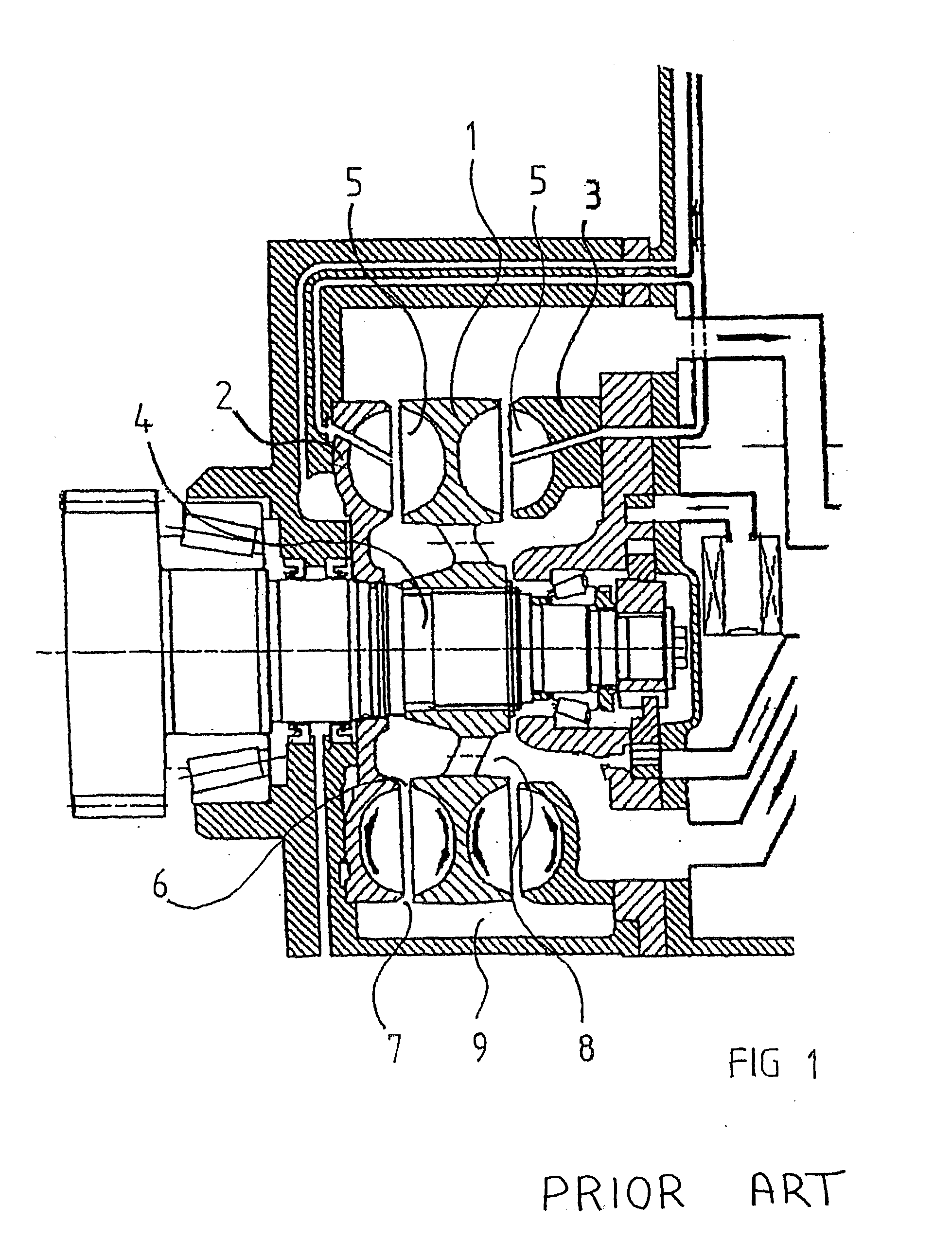
[0028] FIG. 1 shows a cross-section through a retarder in form of a hydrodynamic brake of a motor driven vehicle. The known retarder is accounted in the initial description.

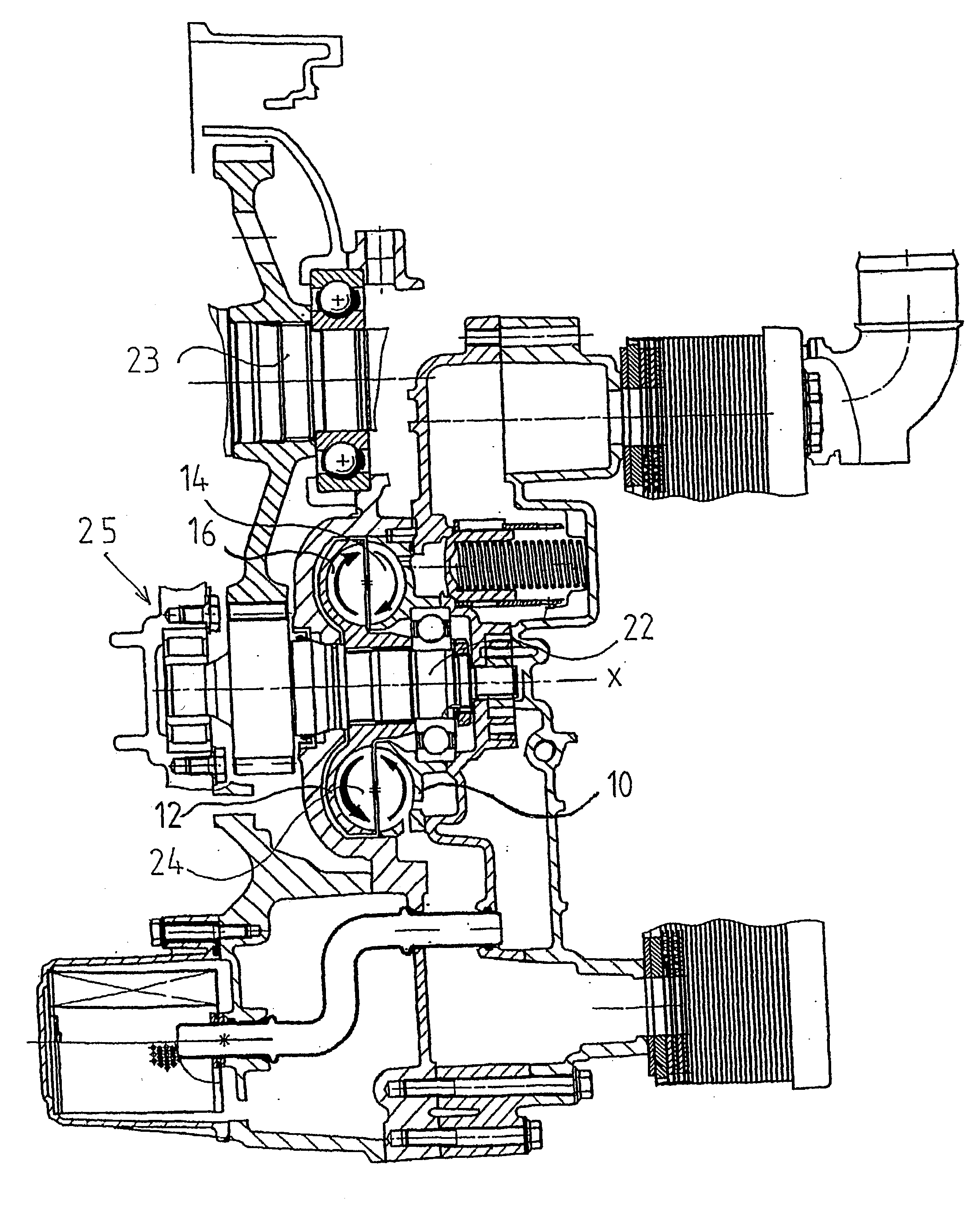
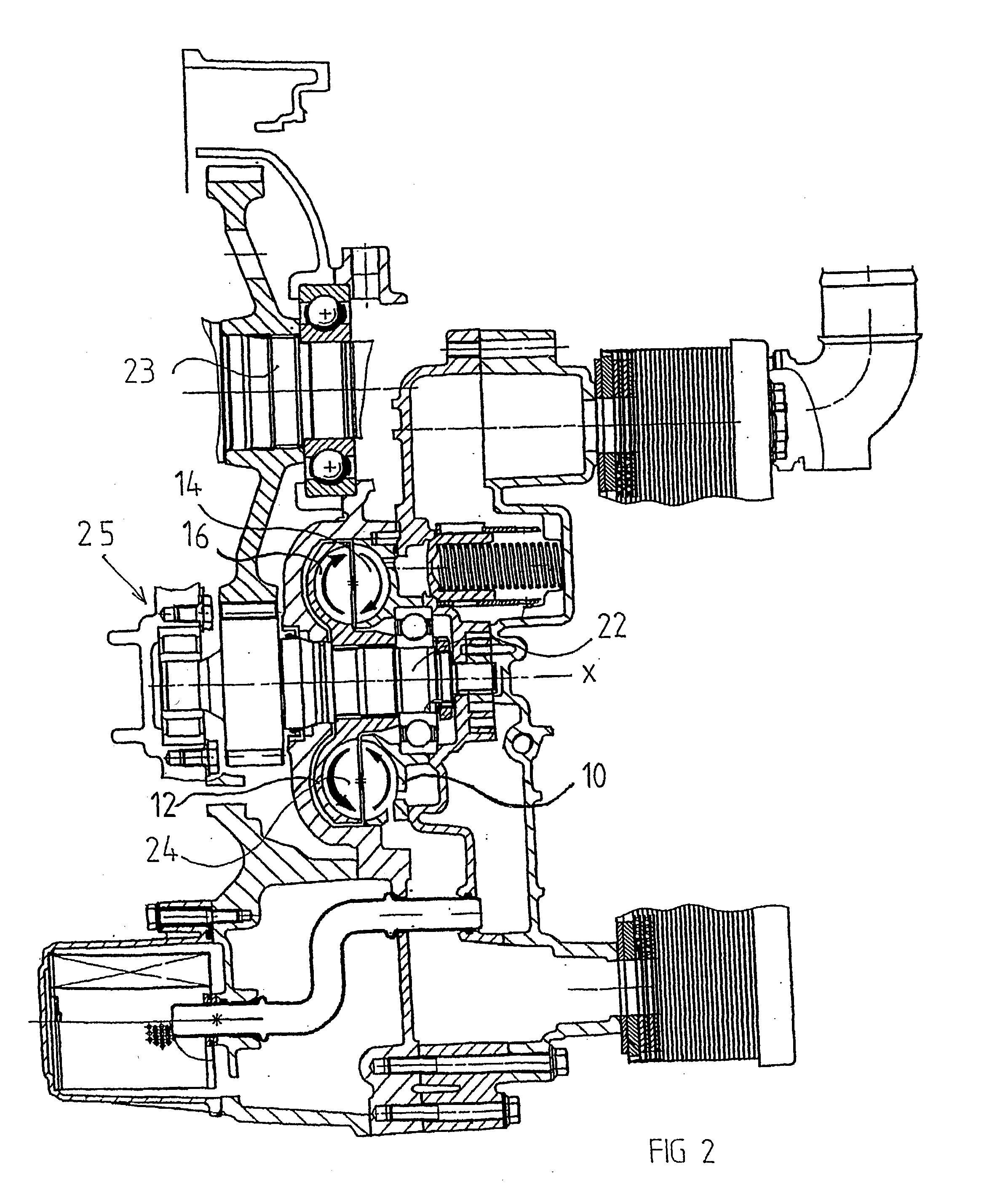
[0029] FIG. 2 shows a cross-section through a portion of a hydrodynamic brake in form of a retarder of a motor driven vehicle according to the invention. The retarder comprises an annular stator 10 and an annular rotor 12 which each comprises an annular recess 14, 16. The stator comprises a plurality of vanes 18 which are provided in the recess 14 of the stator, and the rotor 12 comprises a plurality of vanes 20 which are provided in the recess 16 of the rotor 12, see also FIG. 8. In a mounted state, the annular stator 10 and the annular rotor 12 surround a shaft 22 in such a way that the recesses 14, 16 together form a toroid-shaped space 24. The retarder is connected to the power train of the vehicle, for example at the propeller shaft 23 of the vehicle in connection to the gearbox of the vehicle in order to al...


PUM


Abstract

The present invention relates to a hydrodynamic brake for a vehicle. A stator (10) and a rotor comprises each an annular recess (14) and a plurality of vanes (18) which are provided in the respective parts of the recess (14). The rotor is arranged to rotate in a direction of rotation such that a relatively high pressure is created on a first side of the respective vanes (18) of the stator (10) and a relatively low pressure of a second side of the respective vane (18) of the stator (10). This pressure difference is used for the supply and the discharge, respectively, of the fluid. The respective supply opening (26) is provided in the stator in the vicinity of said second side of a respective vane and the respective discharge opening (28) is provided in the stator in the vicinity of said second side of a respective vane.

Description

BACKGROUND OF THE INVENTION AND PRIOR ART[0001] The present invention relates to a hydrodynamic brake according to the preamble of claim 1.[0002] Auxiliary brakes are principally used in heavy vehicles, such as lorries and buses, in order to avoid wear of the ordinary brakes of the vehicle, such as the service brakes, for example at braking in long downhill slopes. An example of such an auxiliary brake is a hydrodynamic retarder, which generates a braking moment by means of any suitable oil between a stator and a rotor. The stator and the rotor constitute together a toroid-shaped space, which is called torus. The stator as well as the rotor is provided with a plurality of vanes and the oil is guided during the rotation of the rotor by the vanes within the toroid-shaped space. During the braking process, the kinetic energy of the oil is transformed to heat energy. Hereby the oil has to be cooled after it has left the toroid-shaped space. Thereafter the oil may again be supplied to th...

Claims


Application Information

Patent Timeline
Patent Type & Authority Applications(United States)
IPC IPC(8): B60T1/087B60T10/02F16D57/04
CPCB60T1/087F16D57/04F16D57/005B60T10/02
Inventor JONSSON, HANS
Owner SCANIA CV AB
Why Eureka
Try Eureka