
Aerosol dispenser for mixing and dispensing multiple fluid products

Inactive Publication Date: 2004-01-08
SEAQUIST PERFECT DISPENSING FOREIGN INC
View PDF15 Cites 38 Cited by
  • Summary
  • Abstract
  • Description
  • Claims
  • Application Information

AI Technical Summary

Problems solved by technology

One difficulty encountered in dispensing multiple fluids from an aerosol dispenser is the restriction in the operational orientation of the aerosol dispenser.

Method used


Image

  • Aerosol dispenser for mixing and dispensing multiple fluid products
  • Aerosol dispenser for mixing and dispensing multiple fluid products
  • Aerosol dispenser for mixing and dispensing multiple fluid products

Examples


first embodiment

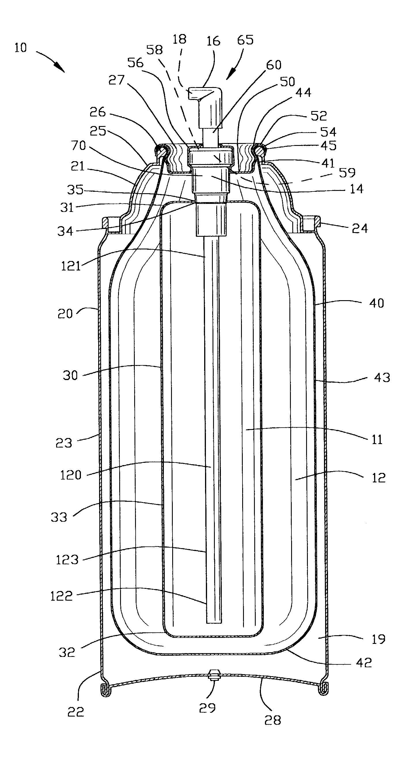
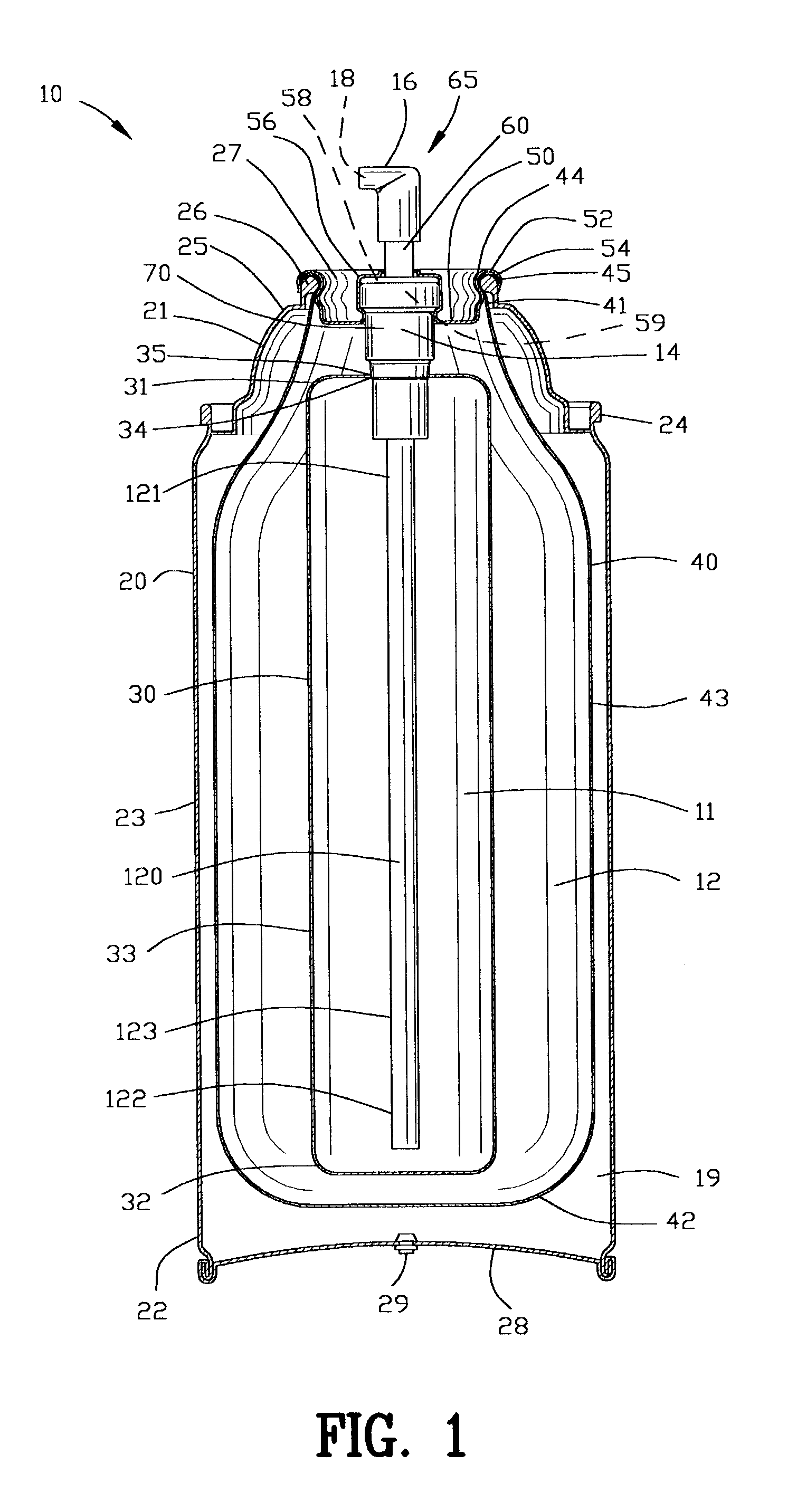
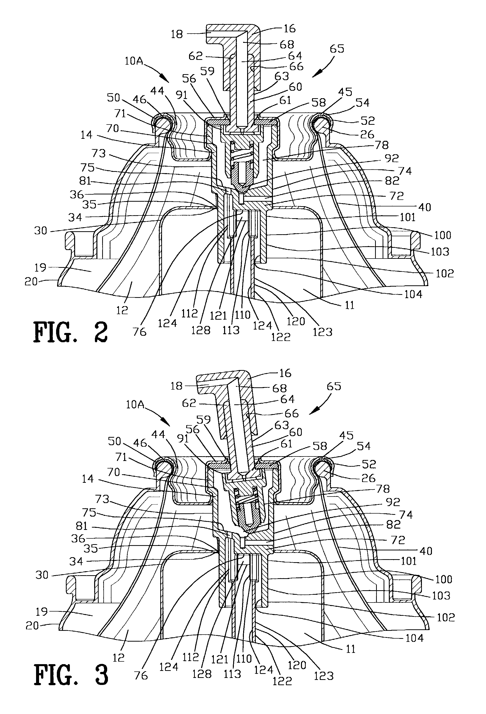
[0058] FIG. 2 is an enlarged view of an improved aerosol dispenser 10A shown in FIG. 1. The valve stem 60 extends between a first end 61 and a second end 62. The valve stem 60 defines an outer surface 63 with a stem passageway 64 extending therein. The actuator 16 includes a socket 66 for frictionally receiving the first end 61 of the valve stem 60. The actuator 16 includes an actuator passage 68 interconnecting the socket 66 to the terminal orifice 18. The socket 66 of the actuator 16 is frictionally secured to the valve stem 60 for enabling the actuator 16 to open the aerosol valve 14.

[0059] The aerosol valve 14 includes a valve body 70 having a top portion 71 and a bottom portion 72 with a sidewall 73 extending therebetween. The bottom portion 72 of the valve body 70 includes an endwall 74 defining an inner surface 75 and an outer surface 76. The valve body 70 defines an internal valve cavity 78 for controlling the flow of the first and second fluid products 11 and 12 through the...

second embodiment

[0093] FIGS. 14-17 are enlarged views of an improved aerosol dispenser 10B shown in FIG. 1. The improved aerosol dispenser 10B shown in FIGS. 14-17 comprises a different aerosol valve 14B, a different actuator 16B, a different valve stem 60B, a different mixer 65B and a different first and second valve element 91B and 92B from the improved aerosol dispenser 10A shown in FIGS. 2-5.

[0094] The valve stem 60B extends between a first and a second end 61B and 62B. The valve stem 60B defines an outer surface 63B with a stem passageway 64B extending therein. The actuator 16B includes a socket 66B for frictionally receiving the first end 61B of the valve stem 60B. The actuator 16B includes an actuator passage 68B interconnecting the socket 66B to the terminal orifice 18B for enabling the actuator 16B to open the aerosol valve 14B.

[0095] The aerosol valve 14B includes a first and a second valve element 91B and 92B disposed in the internal valve cavity 78 of the valve body 70. The first valve ...


PUM


Abstract

An improved aerosol dispenser is disclosed for mixing and dispensing a first and second fluid. The improved aerosol dispenser comprises a valve body sealably mounted to the aerosol container. A first and a second channel is defined in the valve body for providing fluid communication with a valve body cavity of the valve body. A first and a second inner container are located within the aerosol container for communicating with the first and second channels, respectively. A valve assembly comprising a first and a second valve element enables the mixing and dispensing of the first and second fluids from a terminal orifice upon the simultaneous actuation of the first and second valve elements. The invention is also incorporated into the process of filling an improved aerosol dispenser with a first and a second fluid products and an aerosol propellant.

Description

[0001] This application claims benefit of U.S. Patent Provisional application serial No. 60 / 382,283 filed May 21, 2002. All subject matter set forth in provisional application serial No. 60 / 382,283 is hereby incorporated by reference into the present application as if fully set forth herein.[0002] 1. Field Of The Invention[0003] This invention relates to aerosol dispensing from a terminal orifice and more particularly to an improved aerosol dispenser for simultaneously mixing and dispensing multiple fluids from an aerosol container.[0004] 2. Background Of The Related Art[0005] Over the last half of this century, aerosol valve dispensers have demonstrated to be versatile and efficient systems for dispensing a fluid product. A large variety of different types of fluid products have been used with aerosol valve dispensers over the years. In general, aerosol valve dispensers comprise a container containing a product and a pressurized propellant sealed with the aerosol valve. The actuati...

Claims


Application Information

Patent Timeline
IPC IPC(8): A45D34/04A45D34/00B05B7/04B65DB65D1/00B65D83/00B65D83/38B65D83/46B67D7/70B67D7/78
CPCB65D83/36B65D83/38B65D83/42B65D83/753B65D83/62B65D83/68B65D83/46
Inventor YERBY, PATRICK TIMOTHYNEUHALFEN, MARK
Owner SEAQUIST PERFECT DISPENSING FOREIGN INC
Learn More