Prefabricated thin wall concrete panel

a thin wall, concrete technology, applied in the direction of building components, decoration arts, applications, etc., can solve the problems of time-consuming and expensive construction methods, heavy and cumbersome transportation of most known prefabricated concrete wall panels, and add to the cost of a building structur

Inactive Publication Date: 2004-03-04
PAUL BAILLARGEON ARCHITECTE
View PDF31 Cites 47 Cited by
  • Summary
  • Abstract
  • Description
  • Claims
  • Application Information

AI Technical Summary

Benefits of technology

0013] According to a still further broad aspect of the present invention, there is provided a method of fabricating a wall structure utilizing prefabricated wall panels of the present invention. The method comprises providing a footing on a ground surface and drilling pin-locating holes having precise dimensions at predetermined locations along a top surface of the footing using a leveling instrument to determine the depth of said holes for installing a leveled panel. The said panel is positioned vertically on said footing with said footing-connecting pins projecting into complementary ones of said pin-locating holes and resting on a bottom end of the holes for self-leveling and alignment of a plurality of panels on said footing in side-by-side relationship. Once the panels and the pins are in place, the receiving holes are filled with epoxy which forms a "welding" between the side wall of the holes and the pins.

Problems solved by technology

This is a time-consuming and expensive method of construction.
Also, most known prefabricated concrete wall panels are very heavy and cumbersome to transport.
Accordingly, only a few panels are transported on flatbed trucks at a time to a construction site, and this also adds to the cost of a building structure.

Method used


Image

  • Prefabricated thin wall concrete panel
  • Prefabricated thin wall concrete panel
  • Prefabricated thin wall concrete panel

Examples


Embodiment Construction

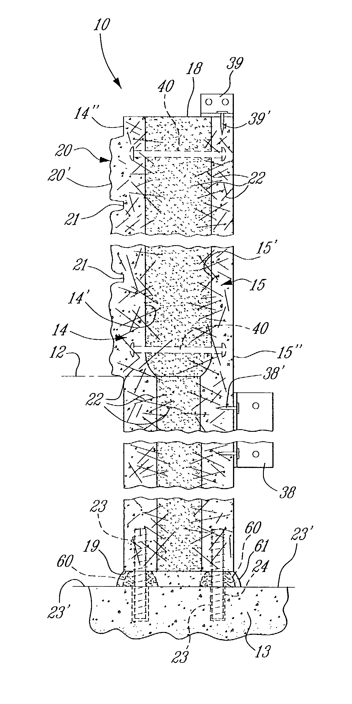
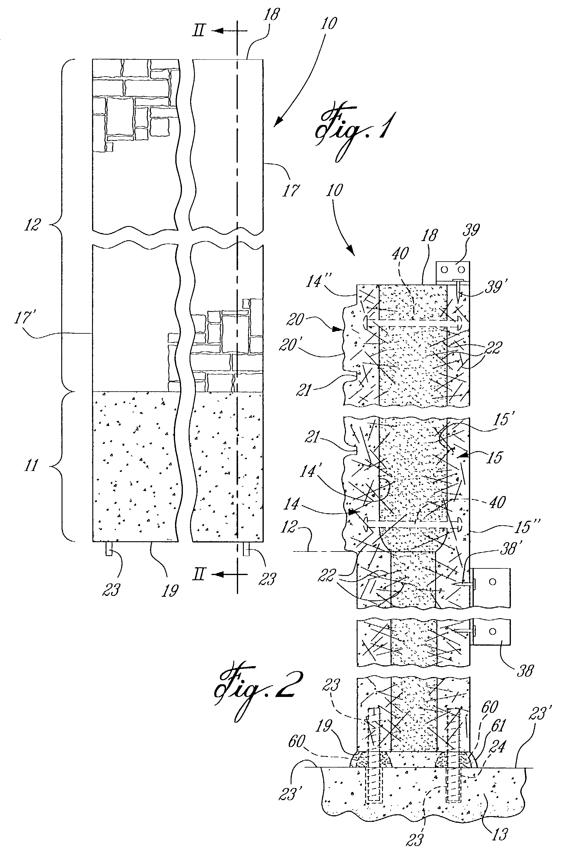
[0022] Referring now to the drawings, and more particularly to FIGS. 1 and 2, there is shown generally at 10 the prefabricated concrete wall panel of the present invention. The wall panel 10 comprises a bottom foundation section 11, which is adapted to be mounted at least partly under a ground surface 12, as shown in FIG. 2, and connected to a footing 13, as will be described later. The prefabricated concrete wall panel 10 also defines a top wall section 12, which is formed integral with the bottom foundation section, in the preferred embodiment herein described. However, in a further embodiment, as illustrated in FIG. 7, only a top wall section 12 is provided that can be secured directly on a top surface of a foundation wall by the pin connections.

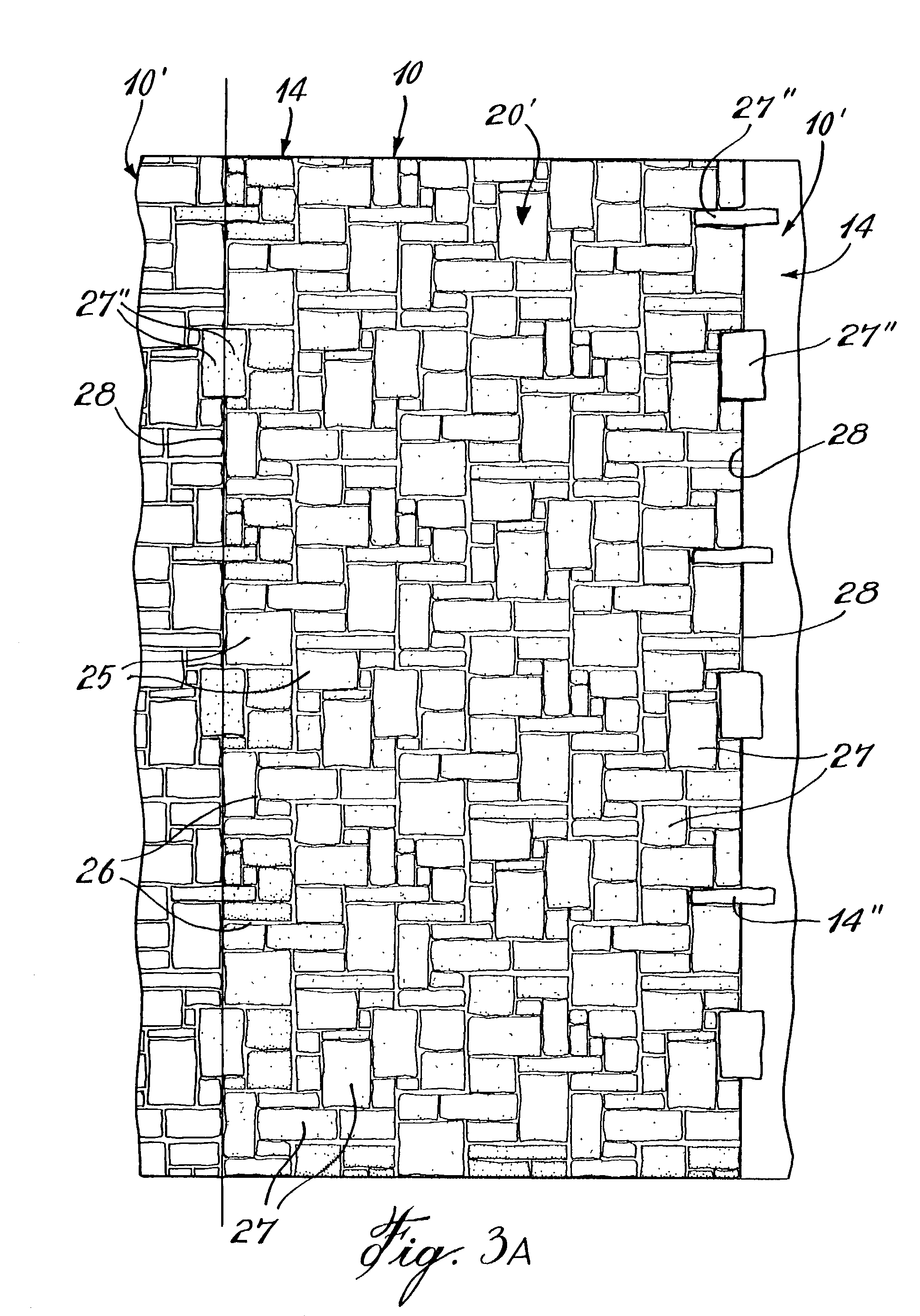
[0023] As better seen from FIG. 2, the concrete wall panel 10 is a composite panel having an outer concrete panel section 14 and an inner concrete panel section 15. The panel sections are spaced from one another by an insulating foam mate...


PUM

PropertyMeasurementUnit
thicknessaaaaaaaaaa
lengthaaaaaaaaaa
depthaaaaaaaaaa

Abstract

A prefabricated concrete wall panel is described which may have a bottom foundation section, when adapted to be mounted at least partly underground, and a top wall section. The wall panel has an outer concrete panel section and an inner concrete panel section spaced from one another by an insulating foam material adhered to an interior surface of the panel sections. The wall panel has opposed flat parallel side walls and top and bottom end walls. The outer concrete panel section has an exterior finished surface. The concrete wall panel also has connecting pins of predetermined equal length projecting from the bottom end wall to provide for support engagement in holes of predetermined depth formed in a top wall of a footing, a floor or a wall, and which provides automatic leveling and alignment of the panel. A method of fabricating a wall structure using the prefabricated wall panel is also disclosed.

Description

[0001] The present invention relates to a composite prefabricated concrete and insulating foam material panel, and including the method of fabricating a concrete wall utilizing such panels.[0002] Various prefabricated or precast concrete wall panels are known for fabricating building structures or walls attached to the structure. The majority of known prefabricated concrete wall panels either utilize these panels as the exterior cladding, with a conventional inner wall being built adjacent an inner surface of the panel and insulated with conventional material, such as wool insulation, or insulated concrete wall panels having insulating polystyrene panels glued thereto. Most of the known prefabricated or precast concrete wall panels are for erection on foundation walls or to be attached to a structure. The assembly of precast concrete wall panels known in the art most often requires metal connectors that are welded together in order to interconnect the panels to a foundation or a str...

Claims


Application Information

Patent Timeline
Patent Type & Authority Applications(United States)
IPC IPC(8): E04C2/04E04C2/288E04C2/34
CPCE04C2/044E04C2/34E04C2/288B32B5/20B32B7/04B32B7/12B32B13/02B32B13/04B32B13/045B32B3/06B32B3/08B32B2250/02B32B2250/03B32B2250/40B32B2266/0278B32B2307/732B32B2607/00
Inventor BAILLARGEON, PAUL
Owner PAUL BAILLARGEON ARCHITECTE
Why Eureka
Try Eureka