Distributing system

a distribution system and distribution system technology, applied in the direction of near-field systems using receivers, coupling device connections, instruments, etc., can solve the problems of difficult to enhance the operation efficiency and necessary tim

Inactive Publication Date: 2004-06-17
TOKYO TSUSHINKI INDS +1
View PDF5 Cites 120 Cited by
  • Summary
  • Abstract
  • Description
  • Claims
  • Application Information

AI Technical Summary

Problems solved by technology

However, the conventional device has such disadvantages that a considerable time is necessary for reading out the address information of the adapter 1 in having a look at them or by the use of a bar code reader, while miss reading and miss input operation may artificially cause in case of reading the address information of the adapter 1 and in case of applying the readout result to the personal computer.
Moreover, since connection operations in the conventional device are carried out to insert each of the connector plugs connected to two ends of the patching cord in view of a connection table indicative of a desired wiring diagram, miss reading of the connection table or miss insertion of the connection plug may cause, while it is difficult to enhance the operation efficiency due to necessity of careful wiring operations.

Method used


Image

  • Distributing system
  • Distributing system
  • Distributing system

Examples


embodiment 1

[0036] (Embodiment 1)

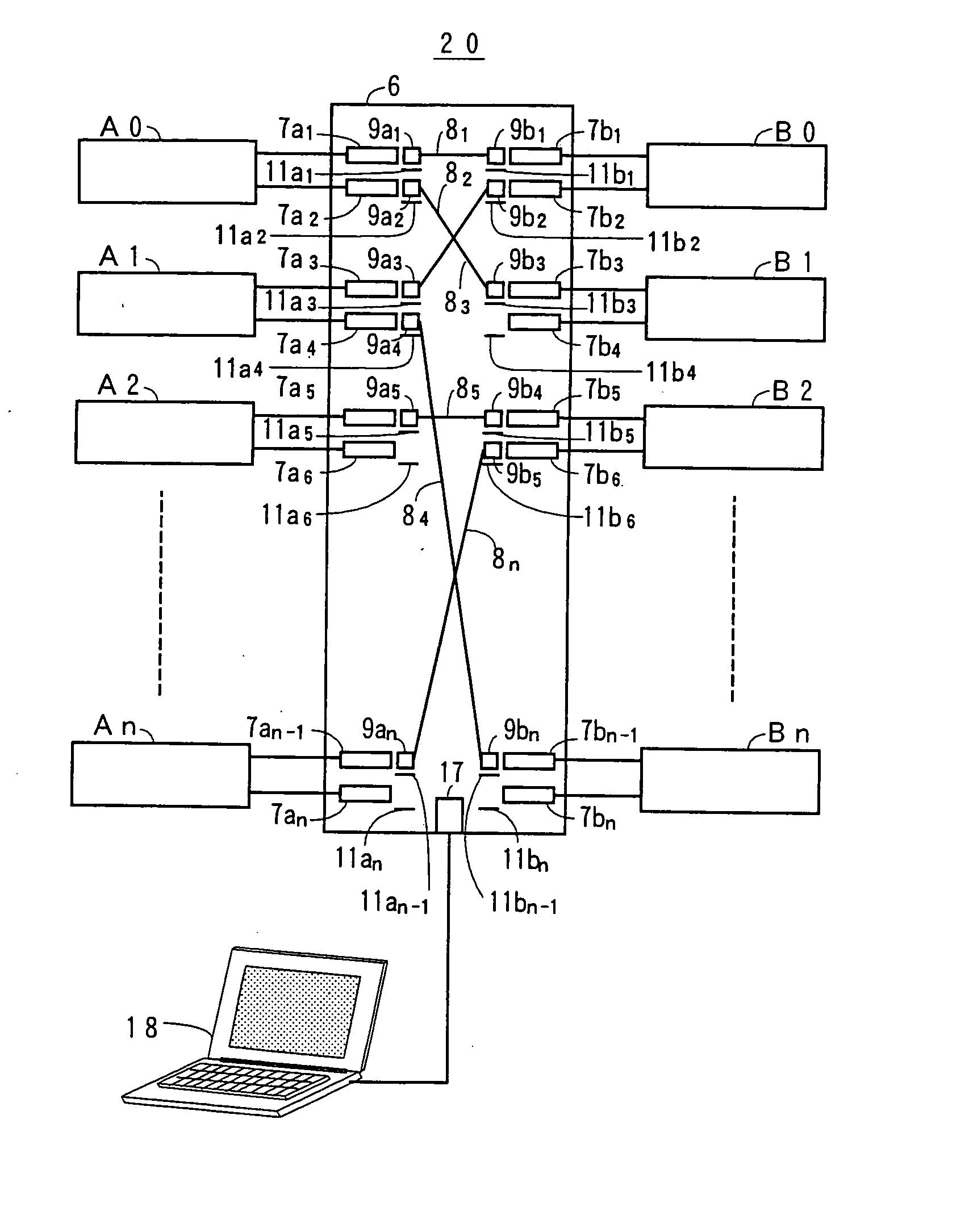
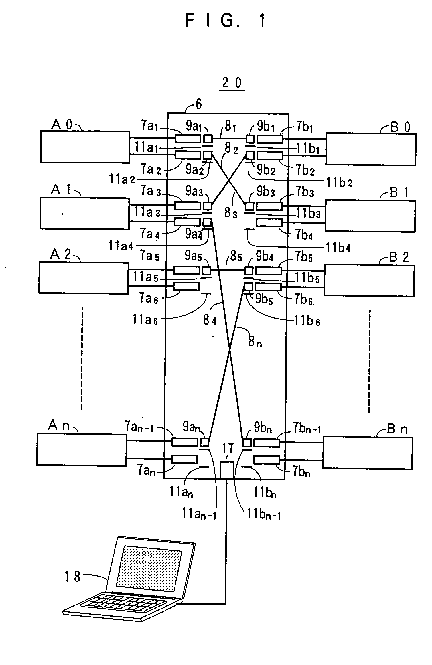
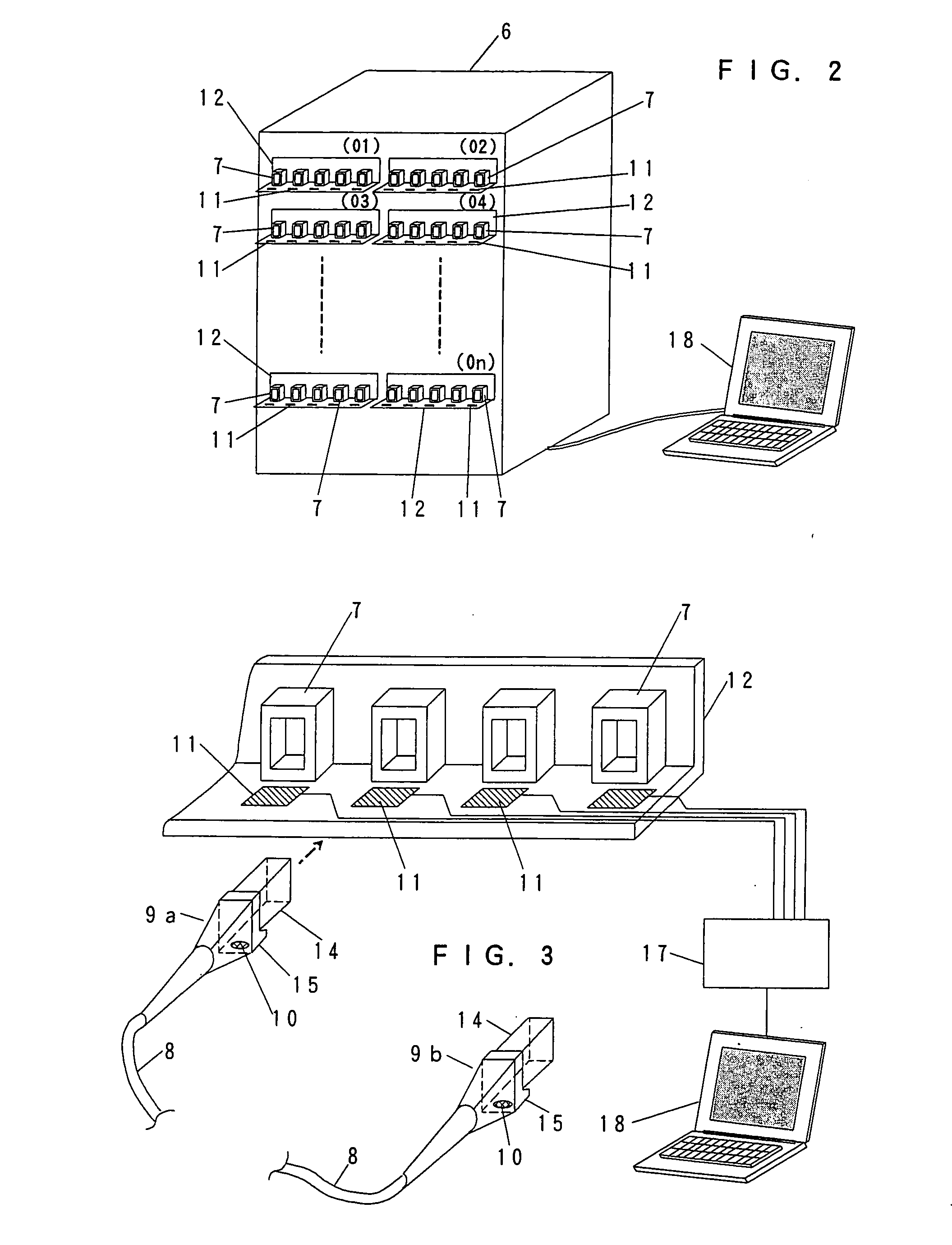
[0037] An embodiment of a distributing system 20 of the present invention will be described with reference to FIG. 1, in which connector adapters and connector plugs are employed as optical type by way of example. In a wiring frame 6 for developing the distributing system 20, many optical connection adapters 7a1 to 7an and 7b1 to 7bn are mounted and connected respectively to equipments A0 to An and B0 to Bn. In order to identify respective one of optical connection plugs 9a1 to 9an and 9b1 to 9bn respectively connected to two ends of the patching cord 8.sub.1 to 8.sub.n as illustrated in FIG. 3 described later, at the neighborhood of the optical connection adapters 7a1 to 7an and 7b1 to 7bn, there is provided antennas 11a1 to 11an and 11b1 to 11bn each capable of untouchably reading out identification information ID stored in memory function units 10 which mounted respectively on the optical connection plugs 9a1 to 9an and 9b1 to 9bn.

[0038] The optical adapters ...

embodiment 2

[0056] (Embodiment 2)

[0057] With reference to FIGS. 9A and 9B, another embodiments of the present invention will be described, in which an indicator is provided at the neighborhood of each of the optical connection adapters 7. In this case, FIG. 9A illustrates a front view of the wiring frame 6, and FIG. 9B is a typical view of a part of the plug board 12 provided on the wiring frame 6, on which the antennas 11 and the indicators 19 are mounted in pairs. The indicators 19 are mounted at the lower surface of the plug board 12, by way of example, on the upper surface side of which each optical adapters 7 are mounted, and further connected through each one of controllers 17 to the personal computer 18. In the above construction, the indicators 19 are successively lightened in green color, for example, in accordance with corrected connection data (i.e. wiring map) of communication equipments stored in the personal computer 18 in order to indicate the operator each position of the optica...


PUM


Abstract

A distributing system 20, comprising: connection lines 3 to two ends of each of which connector plugs 9 with memory function unit 10 capable of untouchably performing, from the outside thereof, writing-in operation and reading-out operation of identification information of the same connector plugs are respectively connected; plug boards 6 mounted on the distributing system; adapters or receptacles 7, mounted separately on the plug boards and connected respectively to communication lines, for coupling to each of the connector plugs; antennas 11 positioned at the neighborhood of each of the adapters or receptacles for untouchably writing-in operation into and reading-out operation of the address information from the memory function unit when each of the connector plugs is coupled to desired one of the adapters or receptacles; and a data processing and display device 17,18, connected to the antennas, comprising memory means for storing a wiring table indicative of desired mutual relationship between said addresses information of said adapters or receptacles and said identification information of the connector plugs, and display means for displaying desired parts of information on the wiring table. The identification information of each of the connector plugs coupled to one of said adapters or receptacles specified from said mutual relationship is displayed on the display means and stored in the memory means.

Description

BACKGROUND OF INVENTION[0001] The present invention relates to a distributing system for connecting a line cable or an office cable to patching cords.[0002] There has been proposed a conventional communication system, as shown in FIG. 10A, in which equipments A0 to An are mutually connected to equipments B0 to Bn. In order to change connection wiring between the equipments A0 to An and the equipments B0 to Bn, a distributing system 2 has been employed in which adapters 1a1 to 1an and adapters 1b1 to 1bn are respectively connected to equipments A0 to An and equipments B0 to Bn. In this case, desired change of connection wiring between the equipments A0 to An and the equipments B0 to Bn can be performed by changing-over with patching cords 3.sub.1 to 3.sub.n between desired pairs of adapters of a plurality of adapters 1 provided on plug boards 6 in a distributing system 2.[0003] Optical cables and metal cables are employed as communication lines for data communication equipments, whil...

Claims


Application Information

Patent Timeline
Patent Type & Authority Applications(United States)
IPC IPC(8): G02B6/38G02B6/36G06K17/00G06K19/00G06K19/07H01R13/639H01R13/641H04B5/02
CPCG02B6/3895H01R2201/06H01R13/6392G02B6/3897
Inventor SAGO, MASUYUKIENOMOTO, MASANORIAITA, HITOSHISATO, KATSURAMORIYAMA, TOKIHARUOOBAYASHI, TAKAYUKISASABE, AKIHIDE
Owner TOKYO TSUSHINKI INDS
Why Eureka
Try Eureka