Brake head positioner

Inactive Publication Date: 2004-07-01
WESTINGHOUSE AIR BRAKE TECH CORP
View PDF14 Cites 8 Cited by
  • Summary
  • Abstract
  • Description
  • Claims
  • Application Information

AI Technical Summary

Benefits of technology

0006] It is, therefore, one of the primary objects of the present invention to provide a brake head positioner which provides for even brake shoe clearance for each brake application and release throughout the life of the brake shoe and the wheel wear conditions.
0007] It is, therefore, another object of the present invention to provide a brake head positioner w

Problems solved by technology

Use of a prior art brake positioning device can result in the brake shoe touching the wheel tread at either the top or bottom when conditions of no wear or full wear exist among the varying wheel/brake shoe wear parameters.
This can re

Method used


Image

  • Brake head positioner
  • Brake head positioner
  • Brake head positioner

Examples


Embodiment Construction

, particularly, when such description is taken in conjunction with the attached drawing figures and the appended claims.

DESCRIPTION OF THE DRAWING

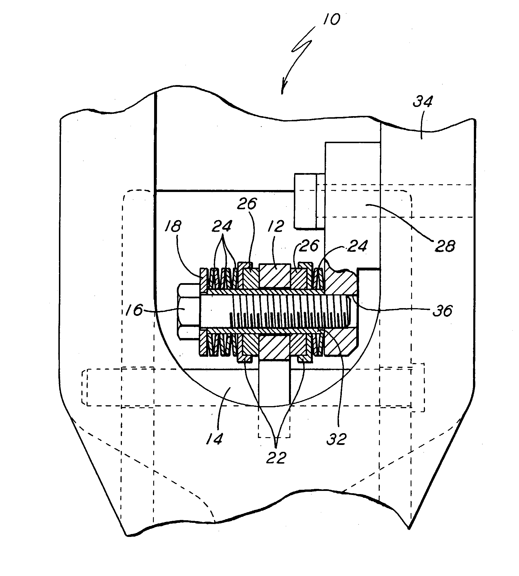
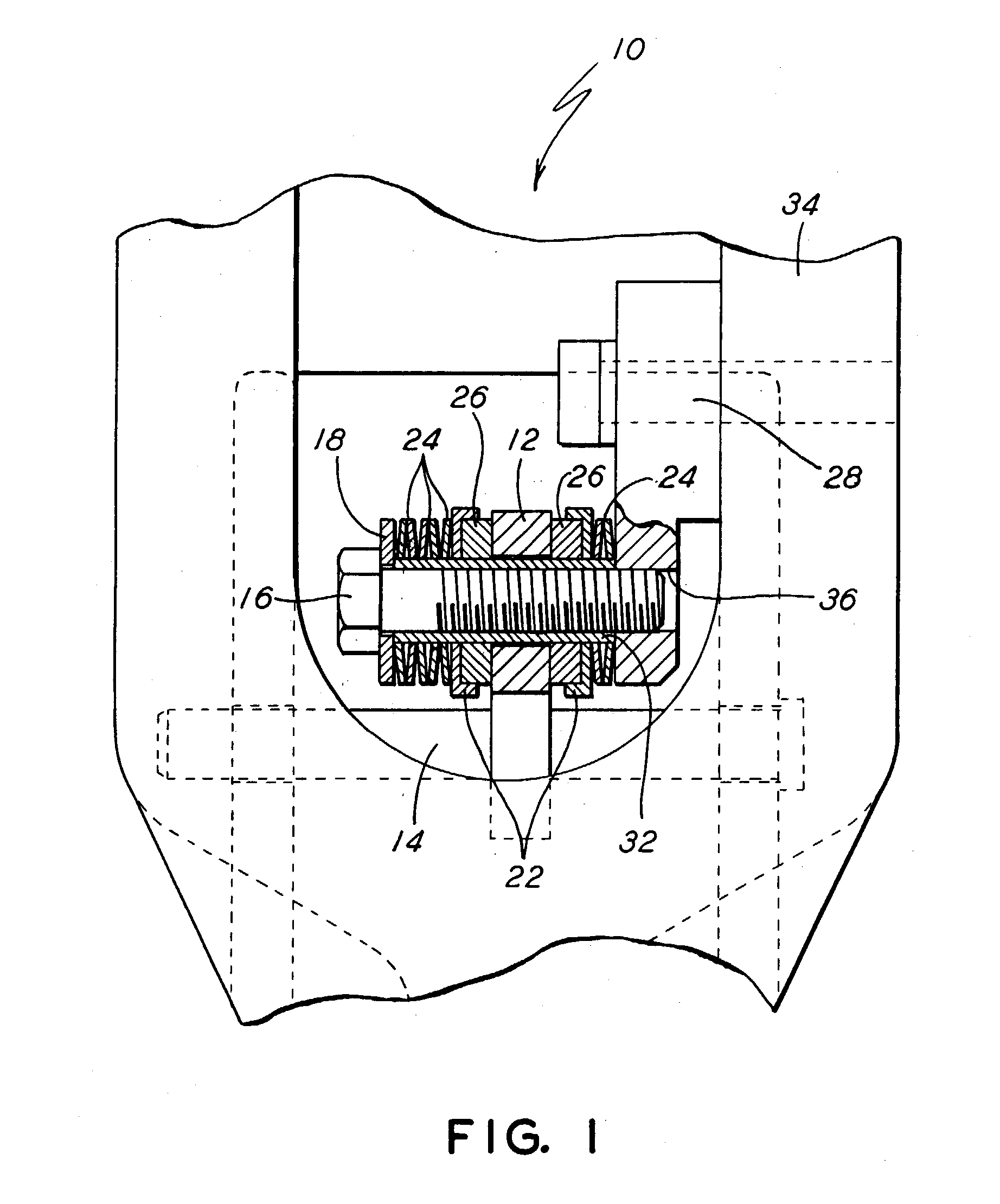
[0010] FIG. 1 is a side elevational view of the present invention, partially in cross section.

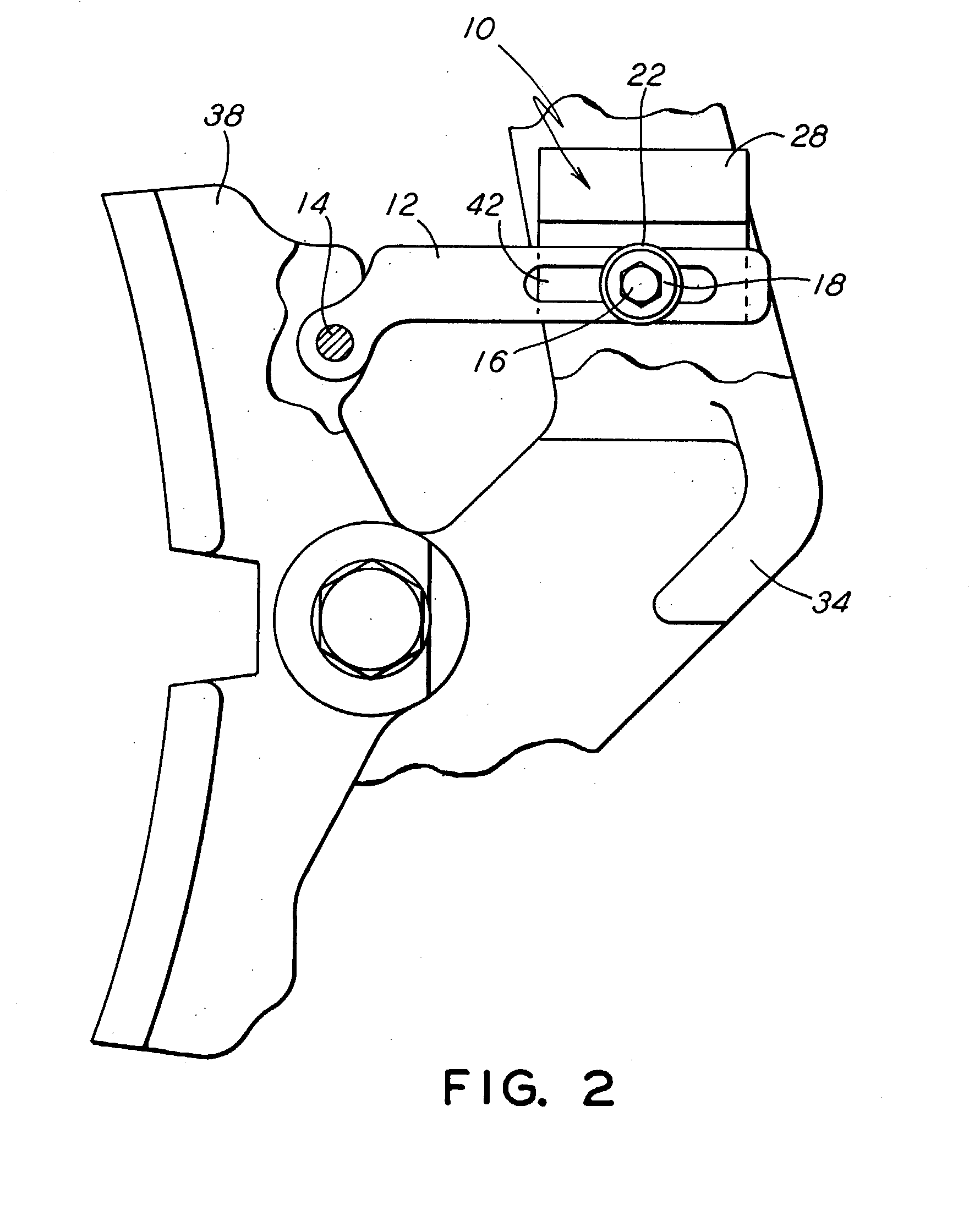
[0011] FIG. 2 is a side view of the present invention connected to a brake shoe.

DETAILED DESCRIPTION OF THE PRESENTLY PREFERRED EMBODIMENT

[0012] Prior to proceeding to a much more detailed description of the present invention, it should be noted that identical components which have identical functions have been identified with identical reference numerals throughout the several views illustrated in the drawing figures for the sake of clarity and understanding of the invention.

[0013] Referring initially to FIG. 1 a brake head positioning means constructed according to the present invention is generally indicated by reference numeral 10. The brake head positioning means 10 of the present invention generally includes a variable distancing means (12),...


PUM


Abstract

A brake head positioning means for railcar braking systems. The brake head positioning means is comprised of an attachment means that is engageable with a railcar hanger arm for attaching such brake head positioning means to such railcar hanger arm. An extension means that is engageable with and extends substantially perpendicular to and outwardly from such attachment means is also included. The extension means provides sliding engagement and enables a biasing force to be achieved. Also included is a variable distancing means which is disposed for sliding engagement with and is substantially perpendicular to such extension means adjacent a first end thereof, and is engageable with a brake head adjacent a second end thereof. A biasing means, disposed around and slideably engageable with such extension means for providing a bias to such variable distancing means during service is further included.

Description

[0001] The present invention generally relates to a brake head positioning device. More particularly, the invention relates to a brake head positioning device that is universally mountable and offers uniform brake shoe clearance.[0002] The use of brake head position devices in the railway industry is well known. They are utilized in the quest to obtain uniform brake shoe wear, which in turn prolongs brake shoe life and offers the economies associated with such a result.[0003] Prior art brake head position devices use a brake head positioning spring consisting of metal friction washers and springs to hold the brake head for even brake shoe clearance upon release of the brake. These prior art designs are a compromise as they are optimized for mid-brake shoe and wheel wear conditions. Use of a prior art brake positioning device can result in the brake shoe touching the wheel tread at either the top or bottom when conditions of no wear or full wear exist among the varying wheel / brake sh...

Claims


Application Information

Patent Timeline
IPC IPC(8): F16D49/00
CPCF16D49/00F16D65/54F16D65/42
Inventor KORLESKI, FRANK J.MOORE, ROLAND S.
Owner WESTINGHOUSE AIR BRAKE TECH CORP
Why Eureka
Try Eureka