This helps you quickly interpret patents by identifying the three key elements:
Problems solved by technology
Method used
Benefits of technology
Benefits of technology
[0012] This invention has been made to provide a solution to the aforementioned problem of the prior art. Specifically, it is an object of the invention to provide a permanent-magnet rotating machine which can efficiently reduce cogging torque and torque ripples compared to a case where permanent magnets are skewed by a theoretically determined row-to-row skew angle.
Problems solved by technology
This phenomenon known as "cogging" causes not only vibrations and noise but also deteriorattion of controllability of the rotating machine.
Even if the theoretically determined row-to-row skew angle .theta.m is applied to an actual rotating machine, however, it is considered still insufficient for reducing the cogging torque.
While a leakage flux that causes the cogging torque could occur at joints between the permanent magnet rows and on the interior of the rotor core, for instance, a leakage flux occurring inside the stator core is a major cause of the cogging torque.
As stated above, the conventional skewed magnet row arrangement used in the rotating machine is associated with the problem that the cogging torque can not be reduced sufficiently since the theoretically determined skew angle is used the row-to-row skew angle.
Method used
Image
Click on the blue label to locate the original text in one second.
Reading with bidirectional positioning of images and text.
Examples
first embodiment
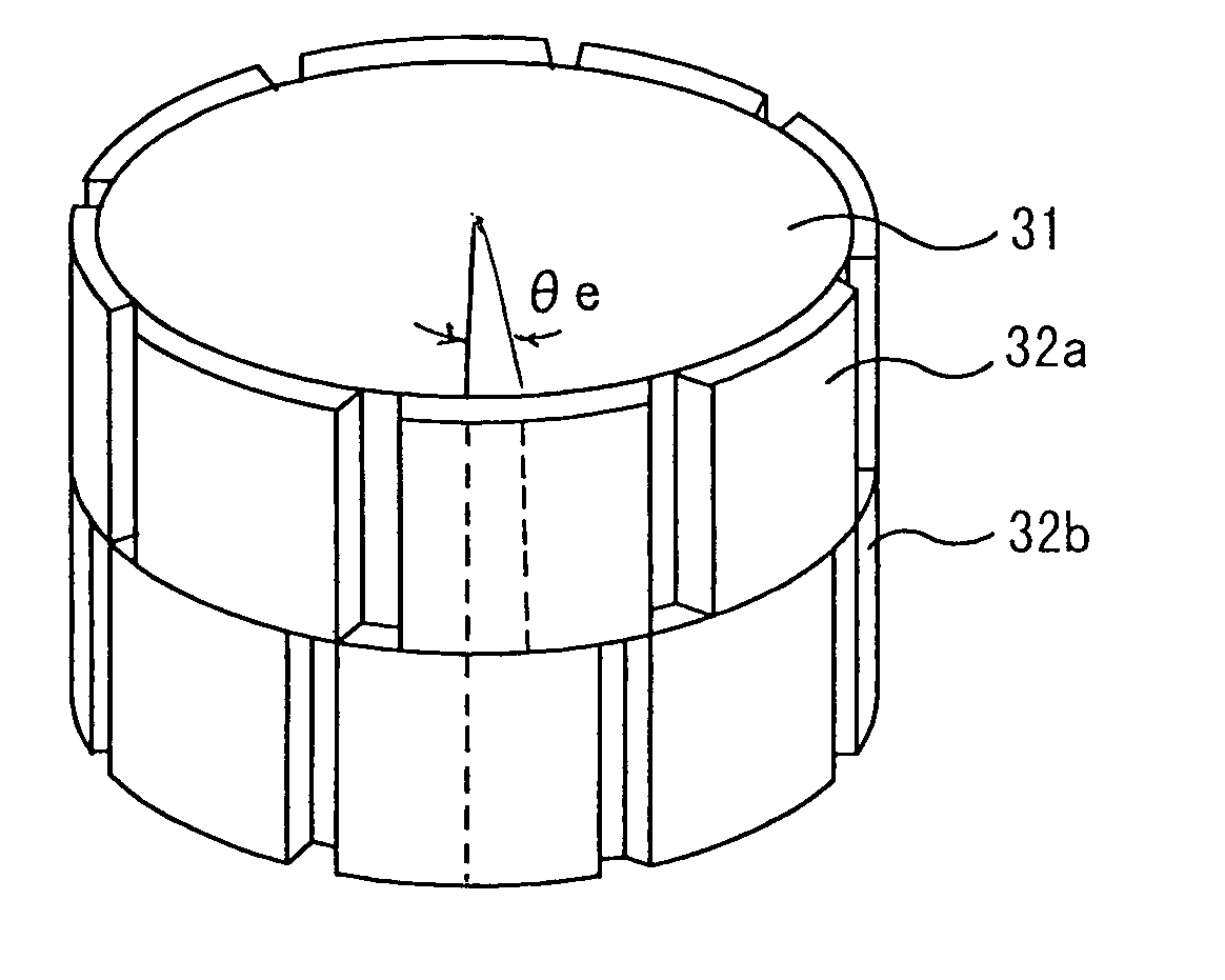
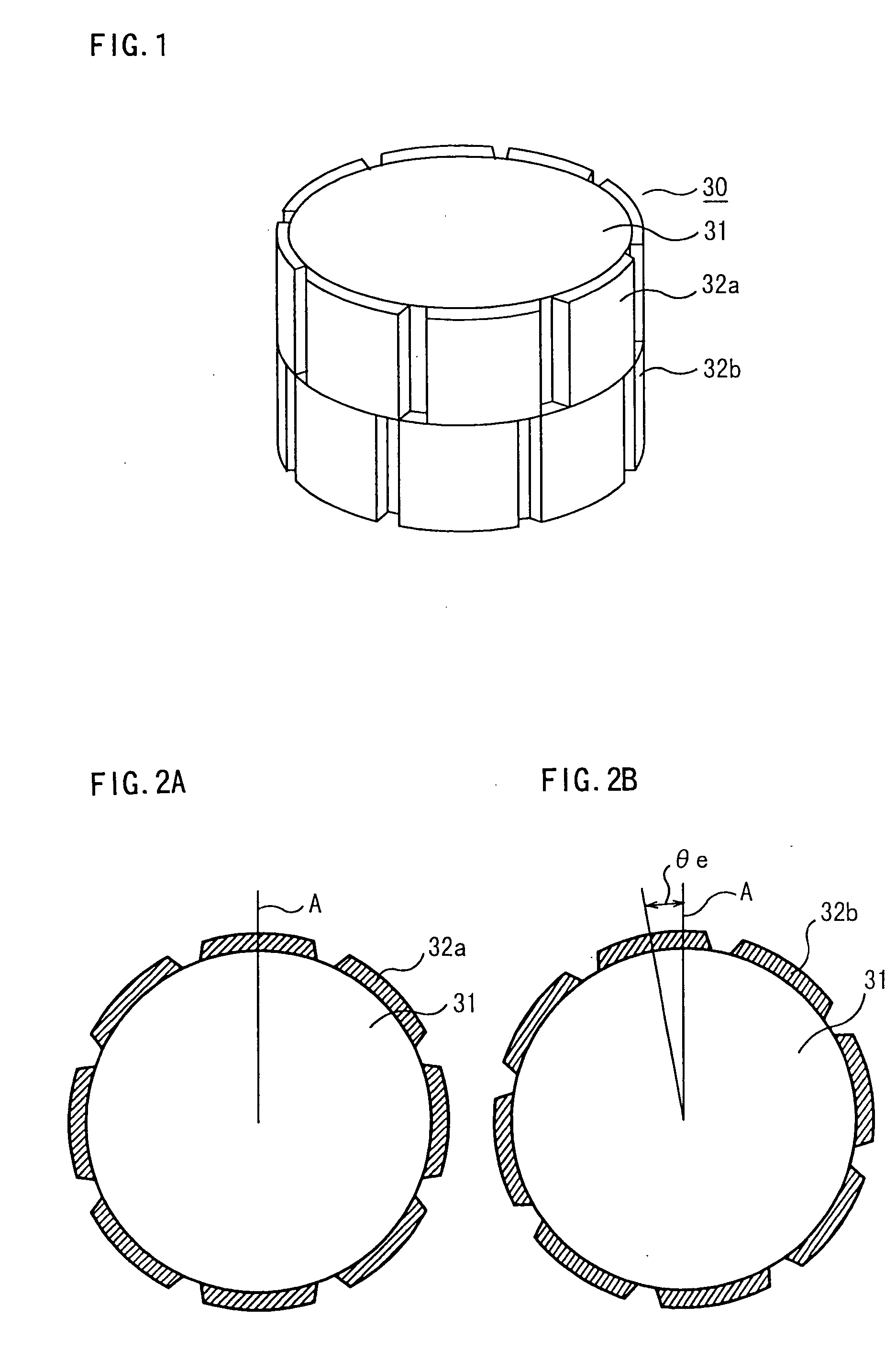
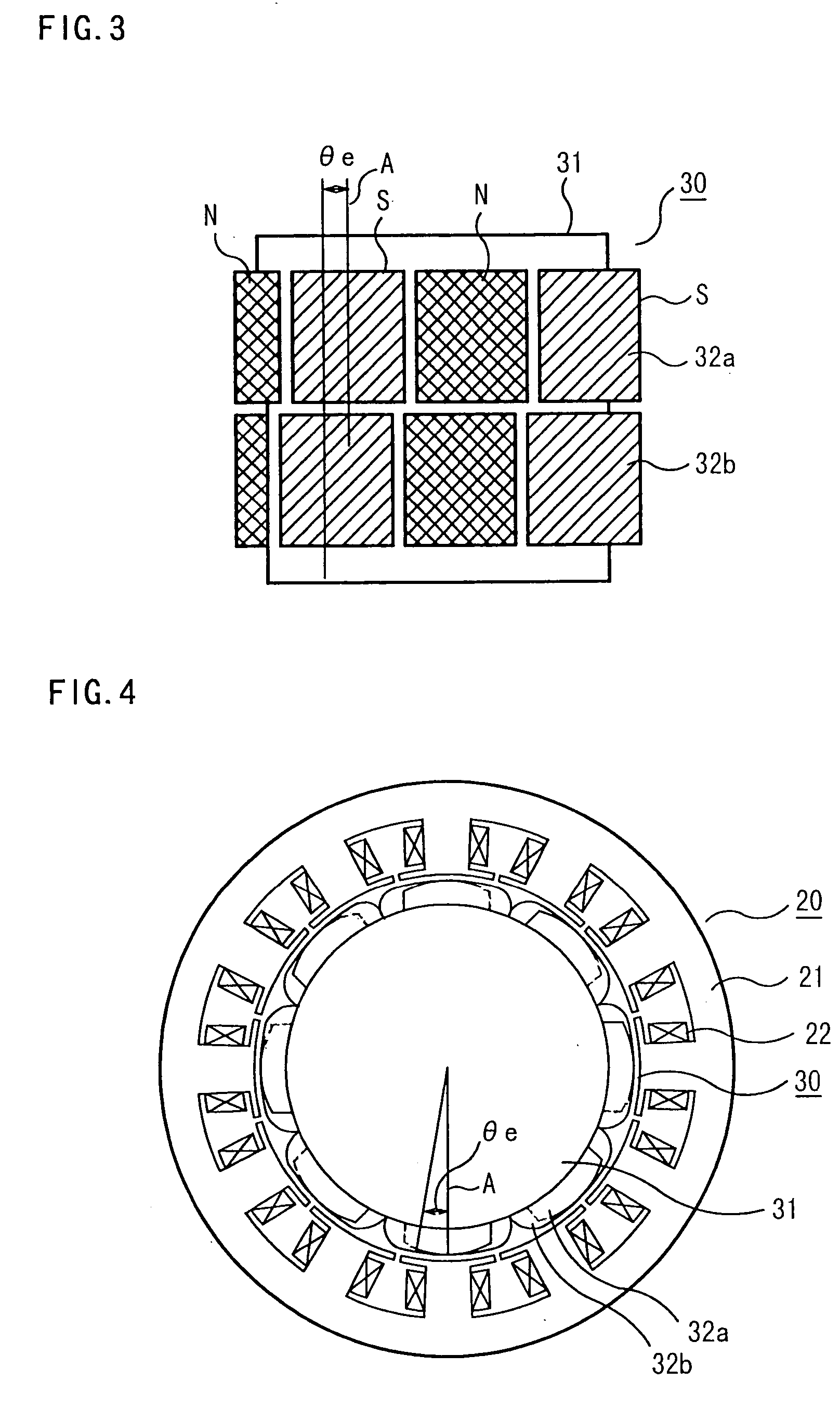
[0037] FIGS. 1, 2A, 2B, 3 and 4 are diagrams showing the construction of a permanent-magnet rotating machine according to a first embodiment of the invention, in which FIGS. 1, 2A, 2B and 3 particularly show the arrangement of permanent magnets 32a, 32b on a rotor 30.
[0038] Referring to FIGS. 1, 2A, 2B and 3, the rotor 30 includes a rotor core 31 and the aforementioned permanent magnets 32a, 32b attached to a curved outer surface of the rotor core 31. The permanent magnets 32a and the permanent magnets 32b are disposed in an upper row and a lower row, respectively, in such a manner that N and S poles are alternately arranged in each row along the circumference of the rotor core 31. The permanent magnets 32a in the upper row and the permanent magnets 32b in the lower row are offset, or skewed, in the circumferential direction of the rotor core 31 by a row-to-row skew angle (electrical angle) .theta.e. As can be seen from the Figures, the number of magnetic poles of the rotor 30 is 8 ...
second embodiment
[0054] FIG. 10 is a perspective view of a rotor core 31 of a permanent-magnet rotating machine according to a second embodiment of the invention, and FIG. 11 is a sectional view of the rotor core 31 of FIG. 10 as viewed along its axial direction, in which elements identical or similar to those shown in FIGS. 1 through 4 are designated by the same reference numerals.
[0055] As shown in FIG. 10, permanent magnets 32a and permanent magnets 32b are arranged in upper and lower rows, respectively, with a row-to-row skew angle .theta.e in the same fashion as so far discussed with reference to the first embodiment.
[0056] The permanent magnets 32a, 32b in the upper and lower rows are attached to the rotor core 31 in such a manner that their N and S poles are skewed as shown in FIG. 11. Specifically, the permanent magnets 32a, 32b are arranged such that the electrical angle between the N and S poles of successive pole pairs in each row is made alternately smaller and larger than normal by as m...
third embodiment
[0059] FIG. 12 is a fragmentary perspective view of a stator according to a third embodiment of the invention, FIG. 13 is a fragmentary perspective view showing a multi-block structure of the stator of the third embodiment, and FIG. 14 is a fragmentary sectional plan view of each block of the stator of the third embodiment.
[0060] This embodiment employs the same structure as the first embodiment in that a lower limit of the row-to-row skew angle .theta.e is set at a value larger than the theoretical angle .theta.s and an upper limit of the row-to-row skew angle .theta.e is set at a value equal to or smaller than a maximum value of the row-to-row skew angle .theta.e at which the cogging torque ratio does not exceed the cogging torque ratio at the theoretical angle .theta.s determined based on the relationship between the cogging torque ratio and the row-to-row skew angle .theta.e and the magnetic property (B-H curves) of the stator core 21.
[0061] The structure of the third embodiment...
PUM
Abstract
A permanent-magnet rotating machine includes a rotor having a rotor core carrying on its curved outer surface multiple permanent magnets arranged in two rows along an axial direction in such a manner that the permanent magnets in one row are skewed from those in the other row in a circumferential direction by a row-to-row skew angle (electrical angle) thetae, and a stator having a cylindrical stator core in which the rotor is disposed, the stator core being provided with stator coils for producing a rotating magnetic field for rotating the rotor. A lower limit of the row-to-row skew angle thetae is set at a value larger than 30 degrees (electrical angle). A cogging torque ratio, or the ratio of a cogging torque occurring in the absence of skew to a cogging torque occurring when the permanent magnets are skewed, at a row-to-row skew angle of 30 degrees is calculated based on the relationship between the cogging torque ratio and the row-to-row skew angle thetae and B-H curve properties of the stator core, and an upper limit of the row-to-row skew angle thetae is set at a value not larger than its maximum value at which the cogging torque ratio does not exceed the calculated cogging torque ratio at 30 degrees.
Description
[0001] 1. Field of the Invention[0002] The present invention relates to a permanent-magnet rotating machine, such as an electric motor, and in particular, to a permanent-magnet rotating machine designed to achieve a reduction in cogging torque.[0003] 2. Description of the Background Art[0004] In an ordinary construction of a permanent-magnet rotating machine, a rotor is disposed inside a stator. The stator has a cylindrical iron core carrying a plurality of stator coils arranged on its curved inner surface to form multiple magnetic poles. The rotor has a rotor core and shaft placed inside the stator so that the rotor can rotate about a central axis of the stator. Permanent magnets are provided on the curved outer surface of the rotor core or embedded in it. The permanent magnets are arranged in such a way that their north (N) and south (S) poles alternate along the surface of the rotor core. The rotating machine causes electric currents to flow through the stator coils to produce a ...
Claims
Application Information
Patent Timeline
Application Date:The date an application was filed.
Publication Date:The date a patent or application was officially published.
First Publication Date:The earliest publication date of a patent with the same application number.
Issue Date:Publication date of the patent grant document.
PCT Entry Date:The Entry date of PCT National Phase.
Estimated Expiry Date:The statutory expiry date of a patent right according to the Patent Law, and it is the longest term of protection that the patent right can achieve without the termination of the patent right due to other reasons(Term extension factor has been taken into account ).
Invalid Date:Actual expiry date is based on effective date or publication date of legal transaction data of invalid patent.

