Permanent-magnet rotating machine

a rotating machine and permanent technology, applied in the direction of magnetic circuit rotating parts, dynamo-electric machines, magnetic circuit shape/form/construction, etc., can solve the problems of deterioration of controllability of rotating machines, insufficient reduction of cogging torque, vibration and noise, etc., to reduce cogging torque and torque ripples. , the effect of efficient reduction

Active Publication Date: 2006-06-27
MITSUBISHI ELECTRIC CORP
View PDF14 Cites 42 Cited by
  • Summary
  • Abstract
  • Description
  • Claims
  • Application Information

AI Technical Summary

Benefits of technology

[0012]This invention has been made to provide a solution to the aforementioned problem of the prior art. Specifically, it is an object of the invention to provide a permanent-magnet rotating machine which can efficiently reduce cogging torque and torque ripples compared to a case where permanent magnets are skewed by a theoretically determined row-to-row skew angle.

Problems solved by technology

This phenomenon known as “cogging” causes not only vibrations and noise but also deterioration of controllability of the rotating machine.
Even if the theoretically determined row-to-row skew angle θm is applied to an actual rotating machine, however, it is considered still insufficient for reducing the cogging torque.
While a leakage flux that causes the cogging torque could occur at joints between the permanent magnet rows and on the interior of the rotor core, for instance, a leakage flux occurring inside the stator core is a major cause of the cogging torque.
As stated above, the conventional skewed magnet row arrangement used in the rotating machine is associated with the problem that the cogging torque can not be reduced sufficiently since the theoretically determined skew angle is used the row-to-row skew angle.

Method used


Image

  • Permanent-magnet rotating machine
  • Permanent-magnet rotating machine
  • Permanent-magnet rotating machine

Examples


first embodiment

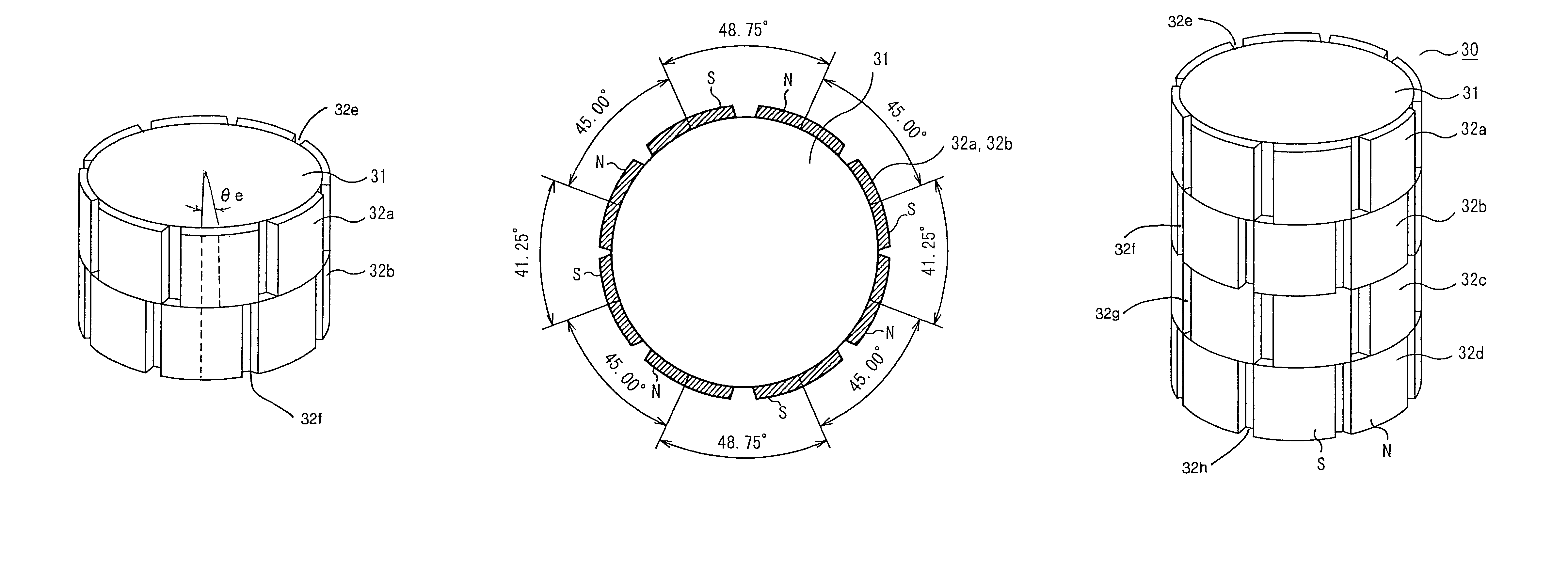
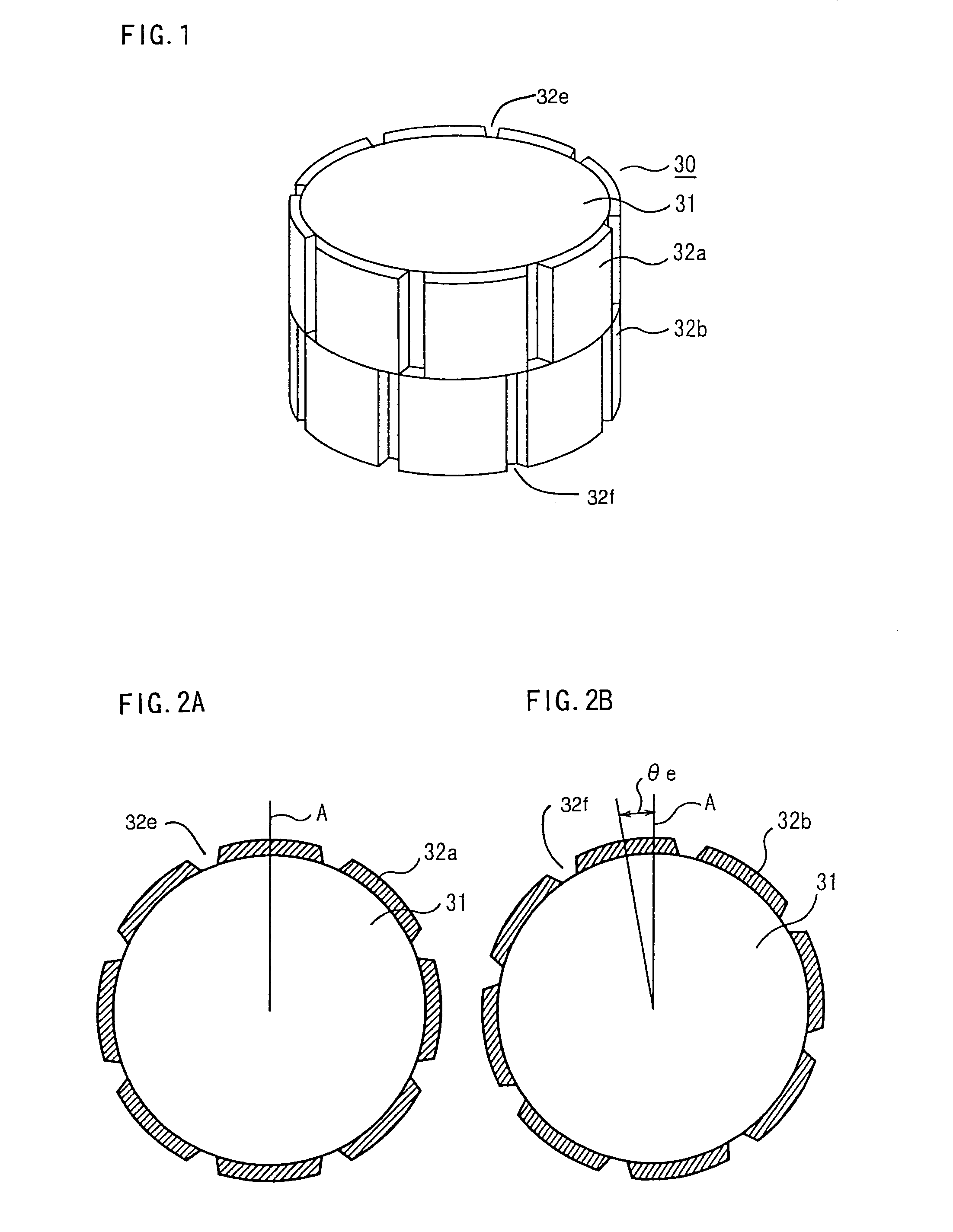
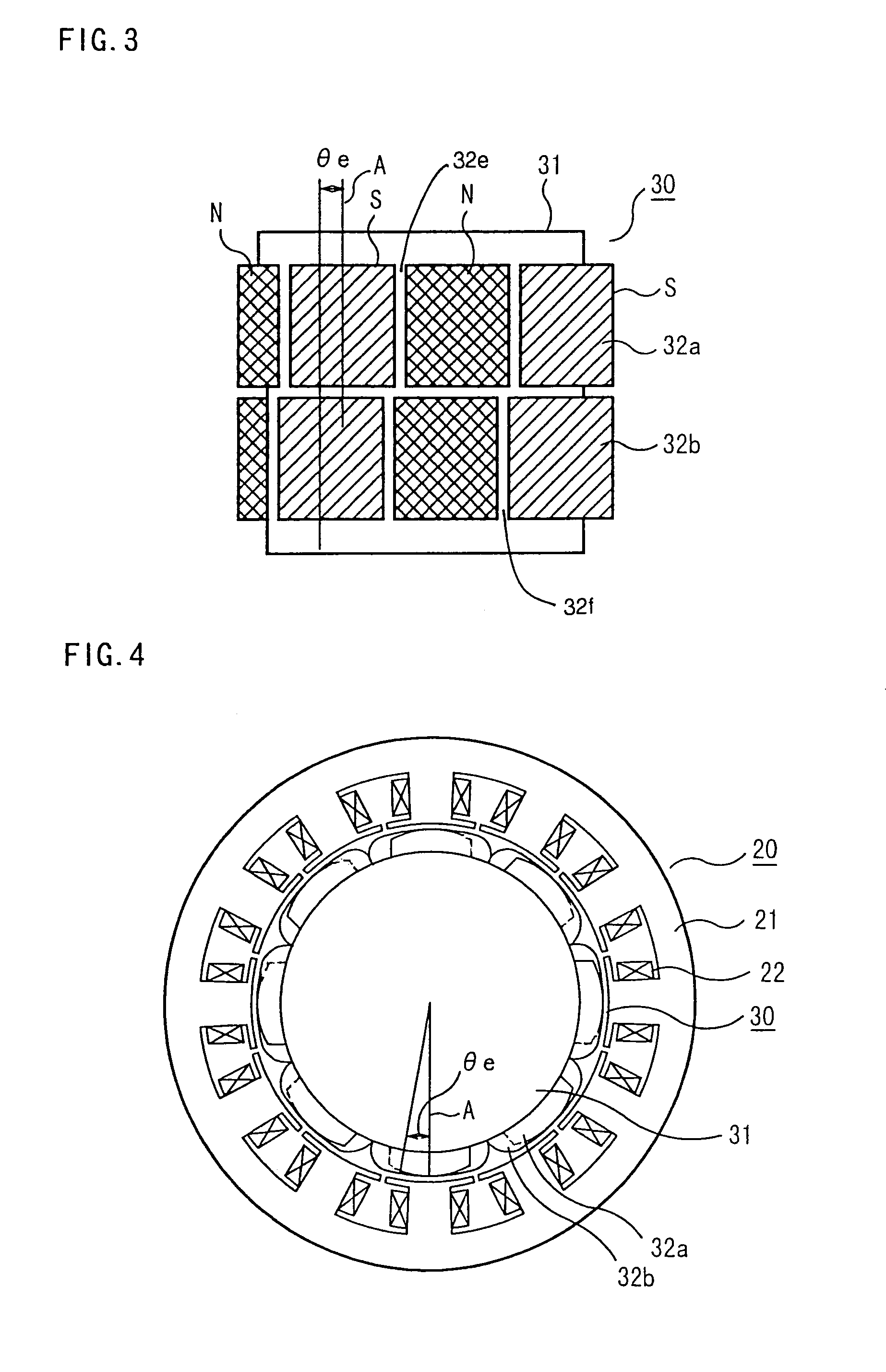
[0037]FIGS. 1, 2A, 2B, 3 and 4 are diagrams showing the construction of a permanent-magnet rotating machine according to a first embodiment of the invention, in which FIGS. 1, 2A, 2B and 3 particularly show the arrangement of permanent magnets 32a, 32b on a rotor 30.

[0038]Referring to FIGS. 1, 2A, 2B and 3, the rotor 30 includes a rotor core 31 and the aforementioned permanent magnets 32a, 32b attached to a curved outer surface of the rotor core 31. The permanent magnets 32a and the permanent magnets 32b are disposed in an upper row and a lower row, respectively, in such a manner that N and S poles are alternately arranged in each row along the circumference of the rotor core 31. Respective gaps 32e and 32f on the circumference of the rotor core 31 separate adjacent pairs of the poles of the magnets 32a and 32b, respectively. The permanent magnets 32a in the upper row and the permanent magnets 32b in the lower row are offset, or skewed, in the circumferential direction of the rotor ...

second embodiment

[0053]FIG. 10 is a perspective view of a rotor core 31 of a permanent-magnet rotating machine according to a second embodiment of the invention, and FIG. 11 is a sectional view of the rotor core 31 of FIG. 10 as viewed along its axial direction, in which elements identical or similar to those shown in FIGS. 1 through 4 are designated by the same reference numerals.

[0054]As shown in FIG. 10, permanent magnets 32a and permanent magnets 32b are arranged in upper and lower rows, respectively, with a row-to-row skew angle θe in the same fashion as so far discussed with reference to the first embodiment.

[0055]The permanent magnets 32a, 32b in the upper and lower rows are attached to the rotor core 31 in such a manner that their N and S poles are skewed as shown in FIG. 11. Specifically, the permanent magnets 32a, 32b are arranged such that the electrical angle between the N and S poles of successive pole pairs in each row is made alternately smaller and larger than normal by as much as 15...

third embodiment

[0058]FIG. 12 is a fragmentary perspective view of a stator according to a third embodiment of the invention, FIG. 13 is a fragmentary perspective view showing a multi-block structure of the stator of the third embodiment, and FIG. 14 is a fragmentary sectional plan view of each block of the stator of the third embodiment.

[0059]This embodiment employs the same structure as the first embodiment in that a lower limit of the row-to-row skew angle θe is set at a value larger than the theoretical angle θs and an upper limit of the row-to-row skew angle θe is set at a value equal to or smaller than a maximum value of the row-to-row skew angle θe at which the cogging torque ratio does not exceed the cogging torque ratio at the theoretical angle θs determined based on the relationship between the cogging torque ratio and the row-to-row skew angle θe and the magnetic property (B-H curves) of the stator core 21.

[0060]The structure of the third embodiment differs from that of the first embodim...


PUM


Abstract

A permanent-magnet rotating machine includes a rotor having a rotor core carrying on a curved outer surface multiple permanent magnets arranged in two rows along an axial direction. The permanent magnets in one row are skewed from those in the other row in a circumferential direction by a row-to-row skew angle (electrical angle) θe. A stator having a tubular stator core in which the rotor disposed includes stator coils for producing a rotating magnetic field for rotating the rotor. A lower limit of the row-to-row skew angle θe larger than 30 degrees (electrical angle). A ratio of cogging torque occurring in the absence of skew to cogging torque occurring when the permanent magnets are skewed, at a row-to-row skew angle of 30 degrees is calculated based on the cogging torque ratio, the row-to-row skew angle θe, and B-H curve properties of the stator core. An upper limit of the row-to-row skew angle θe is not larger than the maximum value at which the cogging torque ratio does not exceed the calculated cogging torque ratio at 30 degrees.

Description

BACKGROUND OF THE INVENTION[0001]1. Field of the Invention[0002]The present invention relates to a permanent-magnet rotating machine, such as an electric motor, and in particular, to a permanent-magnet rotating machine designed to achieve a reduction in cogging torque.[0003]2. Description of the Background Art[0004]In an ordinary construction of a permanent-magnet rotating machine, a rotor is disposed inside a stator. The stator has a tubular iron core carrying a plurality of stator coils arranged on its curved inner surface to form multiple magnetic poles. The rotor has a rotor core and shaft placed inside the stator so that the rotor can rotate about a central axis of the stator. Permanent magnets are provided on the curved outer surface of the rotor core or embedded in it. The permanent magnets are arranged in such a way that their north (N) and south (S) poles alternate along the surface of the rotor core. The rotating machine causes electric currents to flow through the stator ...

Claims


Application Information

Patent Timeline
Patent Type & Authority Patents(United States)
IPC IPC(8): H02K21/22H02K1/27H02K21/14H02K21/16
CPCH02K1/278H02K21/16H02K2201/06
Inventor YAMAGUCHI, SHINICHIKOMETANI, HARUYUKIKIKUCHI, TOMOHIROMIYAZAKI, TAKASHI
Owner MITSUBISHI ELECTRIC CORP
Why Eureka
Try Eureka