Geared expanding structures

a technology of expanding structures and geared parts, which is applied in the direction of girders, toy gears, transoms, etc., can solve the problems of prone to being floppy and its movement would be ill-determined

Active Publication Date: 2004-07-15
HOBERMAN CHARLES
View PDF11 Cites 25 Cited by
  • Summary
  • Abstract
  • Description
  • Claims
  • Application Information

AI Technical Summary

Benefits of technology

0011] This unusual ability to "flip" between two unique folded states allows

Problems solved by technology

Without such pairing of these members, the structure would

Method used


Image

  • Geared expanding structures
  • Geared expanding structures
  • Geared expanding structures

Examples


Embodiment Construction

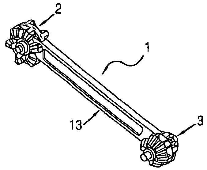
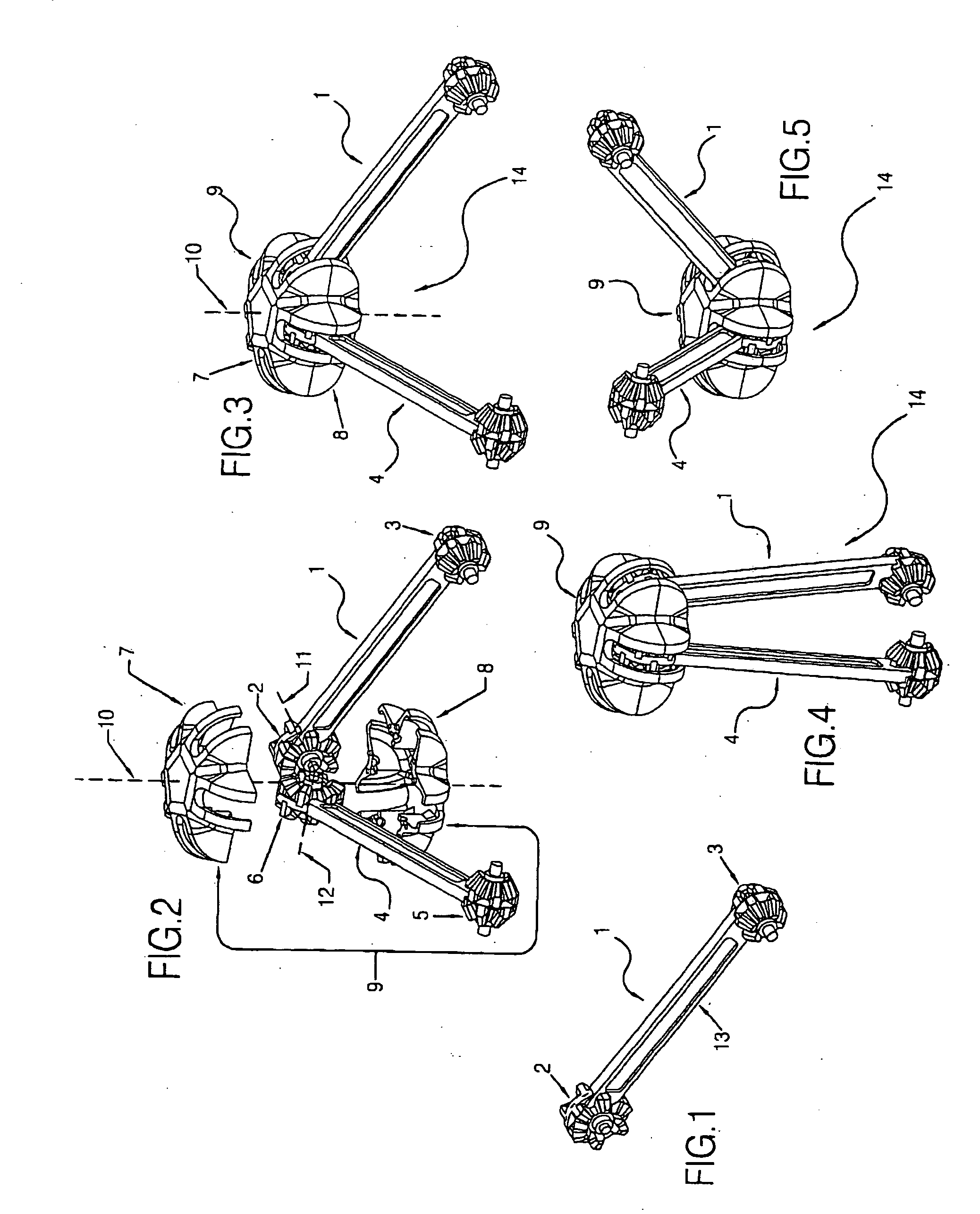
[0077] FIG. 1 shows a link 1 which is comprised of a linear structural element 13 having two geared ends 2 and 3, each consisting of two bevel gears joined back-to-back.

[0078] FIG. 2 shows two links 1 and 4 whose respective gear ends 2 and 6 are engaged with one another. A line 11 is shown oriented along the axis of gear end 2. A second line 12 shown oriented along the axis of gear end 6. Lines 11 and 12 lie in a common plane. A vector 10 which is orthogonal to that plane is shown.

[0079] FIG. 2 also shows an exploded view of a hub element 9 which locates and retains links 1 and 4. Hub element 9 is comprised of two halves 7 and 8 which are oriented such that line 10 forms their central vector.

[0080] FIG. 3 shows an assembly 14 comprised of links 1 and 4 as well as hub 9. Hub 9 is shown in an unexploded view where halves 7 and 8 have been joined together thereby retaining links 1 and 4 such that their respective gear ends 2 and 6 are engaged with one another. Also shown is central lin...


PUM


Abstract

A folding linkage is hereby disclosed that is comprised of four links, each link having a bevel gear on its end, where each link is in geared contact with a neighboring link, such that both links are held together by a hub element that is small relative to the two links. An alternate embodiment of the invention has links that have a spur gear on each end, whereby each gear end is engaged with a central rack (linear gear).

Description

[0001] This application is based on provisional application Serial No. 60 / 439,938, filed Jan. 14, 2003.[0002] U.S. Pat. No. 5,024,031, hereby incorporated by reference as if fully disclosed herein, teaches methods for constructing transformable truss-structures in a variety of shapes. The teachings therein have been used to build structures for diverse applications, including architectural uses, public exhibits and unique folding toys.[0003] One group of embodiments disclosed in the U.S. Pat. No. 5,024,031 patent is expanding structures that are made up of scissor-pairs--linear structural elements that are pinned together by a centrally located pivot. Such scissor-pairs are joined to one another either directly, or via pairs of "hub elements" that attach scissors that lie in different planes. All members of such expanding structures are thus "doubled", whether as strut-pairs or as hub pairs.[0004] The reason for doubling these elements is to synchronize the movement of the structure...

Claims


Application Information

Patent Timeline
IPC IPC(8): A63H31/00A63H33/10E04B1/344E04B7/10E04C3/02E04H1/12
CPCA63H31/00A63H33/107E04B1/3441E04H1/1272E04C2003/023E04C2003/026E04B7/105
Inventor HOBERMAN, CHARLES
Owner HOBERMAN CHARLES
Why Eureka
Try Eureka