Hinge locking carabiner

a carabiner and locking technology, applied in the field of climbing aids, can solve the problems of inability to remove in time, inability to adjust, and significant risk of inadvertent release of ropes or other climbing aids,

Inactive Publication Date: 2004-07-29
CHRISTIANSON TONY
View PDF0 Cites 40 Cited by
  • Summary
  • Abstract
  • Description
  • Claims
  • Application Information

AI Technical Summary

Problems solved by technology

The normally closed, inward opening gate facilitates insertion of climbing aids, but impedes inadvertent removal.
Also, during a fall a carabiner will often slap against the rock causing inertial loads that overcome the closing force of the spring and momentarily open the gate.
Whenever the gate opens, even momentarily, there is significant risk that a rope or other climbing aid will be inadvertently released.
Furthermore, if a sudden load is applied to the carabiner at the instant that the gate is open, the ultimate strength of the carabiner is significantly compromised and very possibly may fail.
Such occurrences are well known by the climbing community and are considered a major problem.
However, extra carabiners for the purpose of parallel placement are undesirable because they add considerably to the weight and bulk that the climber must carry.
Unfortunately, threaded locking sleeves undesirably add bulk and weight to the carabiner.
Threaded locking sleeves are also inherently troublesome.
The threads can become clogged with dirt or ice.
The sleeve can inadvertently screw out of the locked position when the carabiner rubs across the rock.
Furthermore, the gate and threaded sleeve mechanism require precise machining and assembly alignment, both of which add significantly to manufacturing cost.
Sliding and rotary sleeves share the same problems as threaded sleeves, and are especially costly to manufacture.
The increased bulk, weight and cost of the prior art limits the number of locking carabiner that a climber is able to carry during a climb or is willing to buy in the first place.

Method used


Image

  • Hinge locking carabiner
  • Hinge locking carabiner
  • Hinge locking carabiner

Examples


Embodiment Construction

is made with reference to the accompanying drawings wherein like numerals designate corresponding parts in the several FIGS.

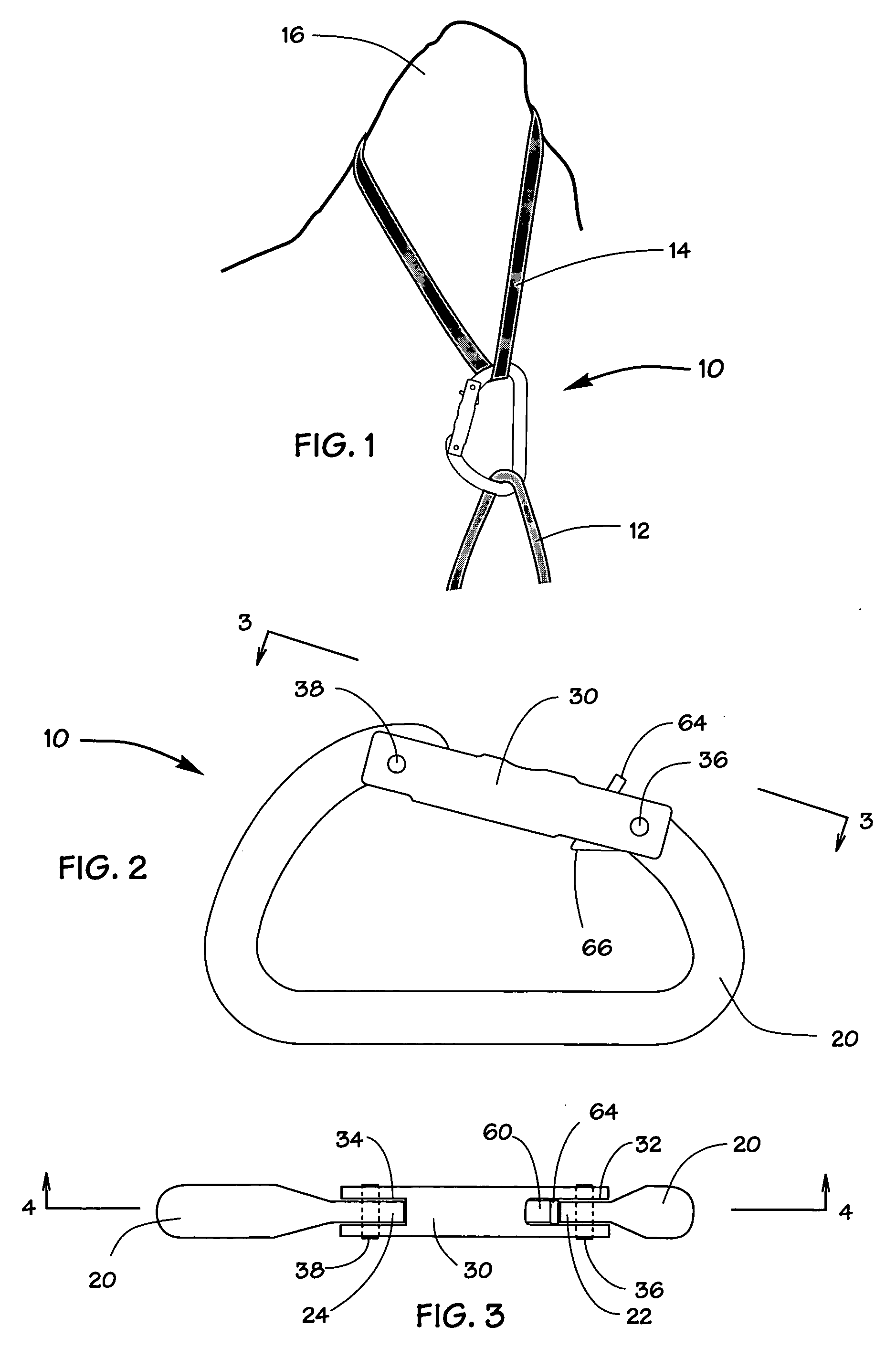
[0023] FIG. 1 is a pictorial view of the inventive carabiner linking rope and webbing.

[0024] FIG. 2 is a side elevation view of a carabiner incorporating the preferred configuration of the inventive locking mechanism.

[0025] FIG. 5 is a top view of the carabiner as seen in the direction 3-3 of FIG. 2.

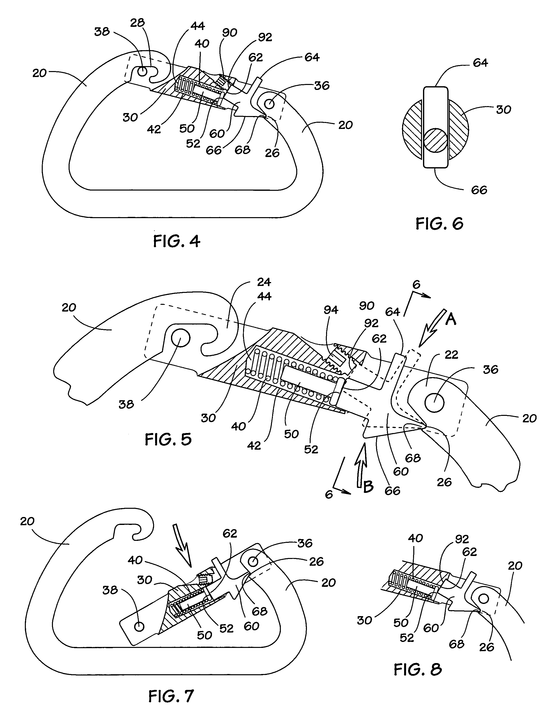
[0026] FIG. 4 is a partial sectional view of the inventive carabiner, taken along a cut corresponding to line 4-4 of FIG. 3, showing the locking mechanism locked.

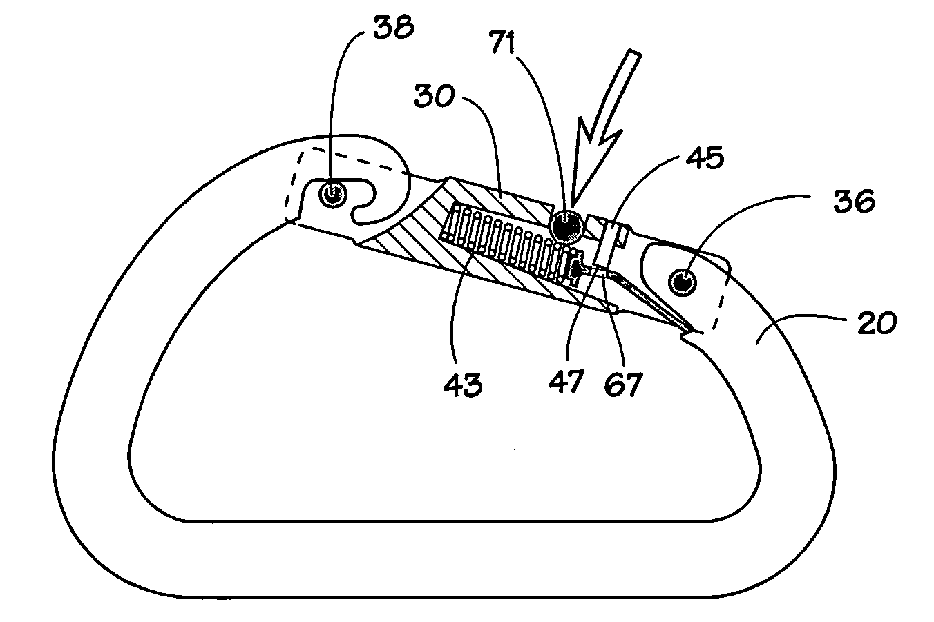
[0027] FIG. 5 is a partial close-up sectional view of the carabiner of FIG. 4.

[0028] FIG. 6 is a sectional view of the carabiner, taken alone a cut corresponding to line 6-6 of FIG. 5.

[0029] FIG. 7 is a partial sectional view of the carabiner of FIG. 4, showing the locking mechanism unlocked and the gate open.

[0030] FIG. 8 is a partial sectional view showing an alternate configuration of the locking mechani...


PUM


Abstract

The instant invention is a compact carabiner locking mechanism contained within the carabiner gate. The locking mechanism incorporates a means to disable the gate return spring mechanism and thereby prevent movement of the gate. A low profile external protrusion on one side of the gate is pushed to unlock the gate return spring mechanism, which allows the gate to be opened. Similarly, another low profile external protrusion on the other side of the gate is pushed to lock the gate return mechanism. The locking and unlocking protrusions are located adjacent the gate hinge so that the carabiner gate can be conveniently unlocked, opened and relocked with one hand.

Description

RELATED APPLICATIONS AND DISCLOSURE DOCUMENTS[0001] The instant invention is a continuation-in-part of application Ser. No. 10 / 309,599 filed Dec. 3, 2002, which claims priority of Provisional Application No. 60 / 339,524 filed Dec. 8, 2001.[0002] The instant application is also related to Disclosure Documents No. 500828 deposited Oct. 5, 2001 and No. 456950 deposited May 25, 1999; and now abandoned Provisional Applications No. 60 / 295,681 filed Jun. 2, 2001 and No. 60 / 197,748 filed Apr. 17, 2000.[0003] 1. Field of the Invention[0004] The instant invention is generally related to climbing aids for rock climbers. More particularly, this invention is related to mechanical devices that link climbing aids together.[0005] 2. Description of the Prior Art[0006] Climbers utilize rope, slings and a variety of mechanical devices as climbing aids to assist and protect their movement over rock. The climbing aids serve as a means to anchor the climber to the rock for the purpose of either preventing...

Claims


Application Information

Patent Timeline
Patent Type & Authority Applications(United States)
IPC IPC(8): F16B45/02
CPCY10T24/45366F16B45/02
Inventor CHRISTIANSON, TONY
Owner CHRISTIANSON TONY
Why Eureka
Try Eureka