
Automated on-line capacity expansion method for storage device

a storage device and automatic technology, applied in the direction of memory address/allocation/relocation, input/output to record carriers, instruments, etc., can solve the problems of simultaneous plurality of users requesting on-line volume expansion, inability to perform on-line volume expansion, and sudden data increas

Inactive Publication Date: 2004-08-19
HITACHI LTD
View PDF10 Cites 60 Cited by
  • Summary
  • Abstract
  • Description
  • Claims
  • Application Information

AI Technical Summary

Problems solved by technology

However, in a large-size site such as a data center where a plurality of enterprises utilize data, there is a possibility of a sudden data increase from computers of the plurality of enterprises and it is necessary to perform the on-line volume expansion at all time.
When using the on-line volume expansion in this condition, there is a case that a request for the on-line volume expansion is simultaneously caused by a plurality of users due to the data increasing as time passes and the logical volume provider may not be able to satisfy the requests.
In the worst case, the on-line volume expansion cannot be performed and the computer operation is stopped.

Method used


Image

  • Automated on-line capacity expansion method for storage device
  • Automated on-line capacity expansion method for storage device
  • Automated on-line capacity expansion method for storage device

Examples


first embodiment

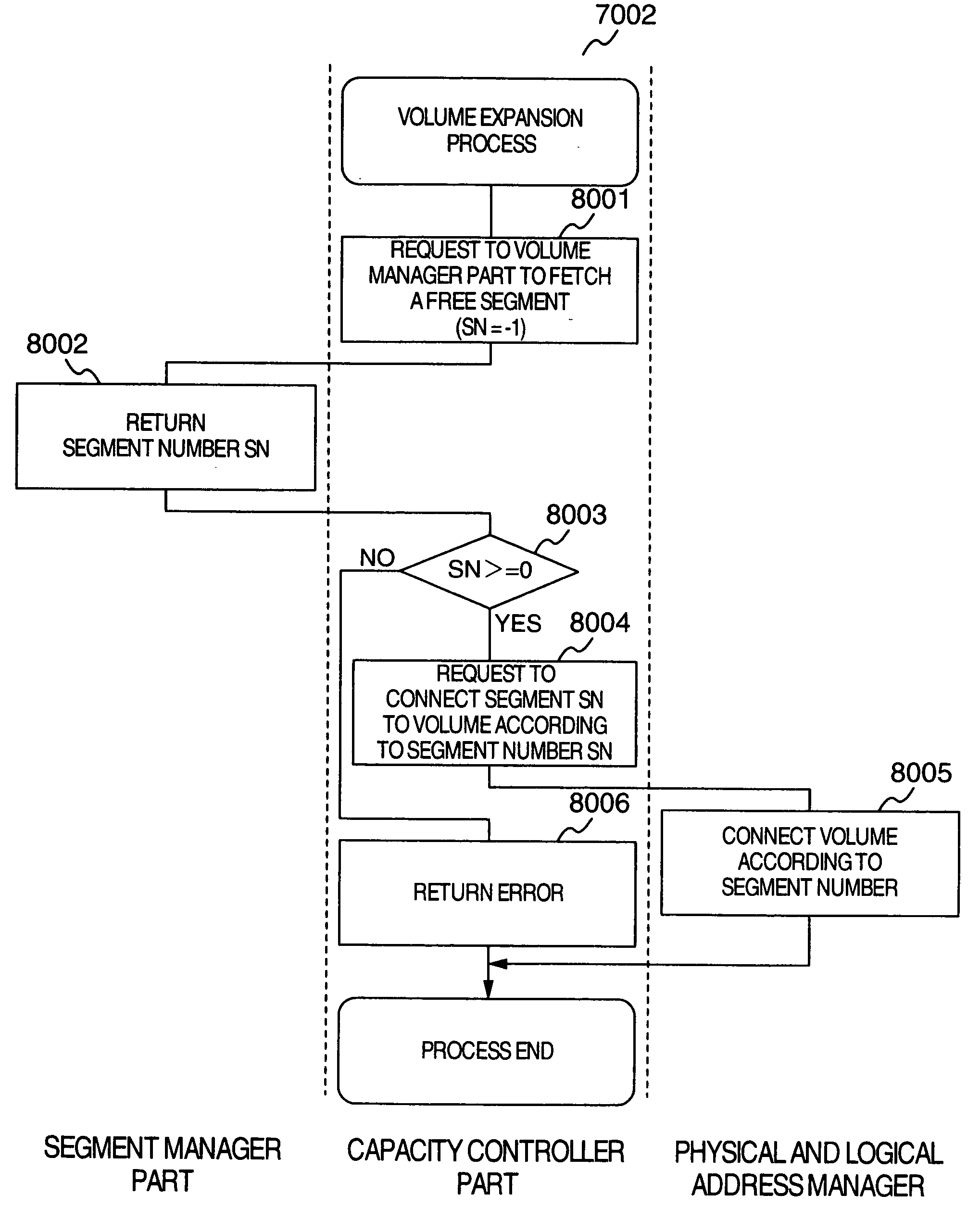
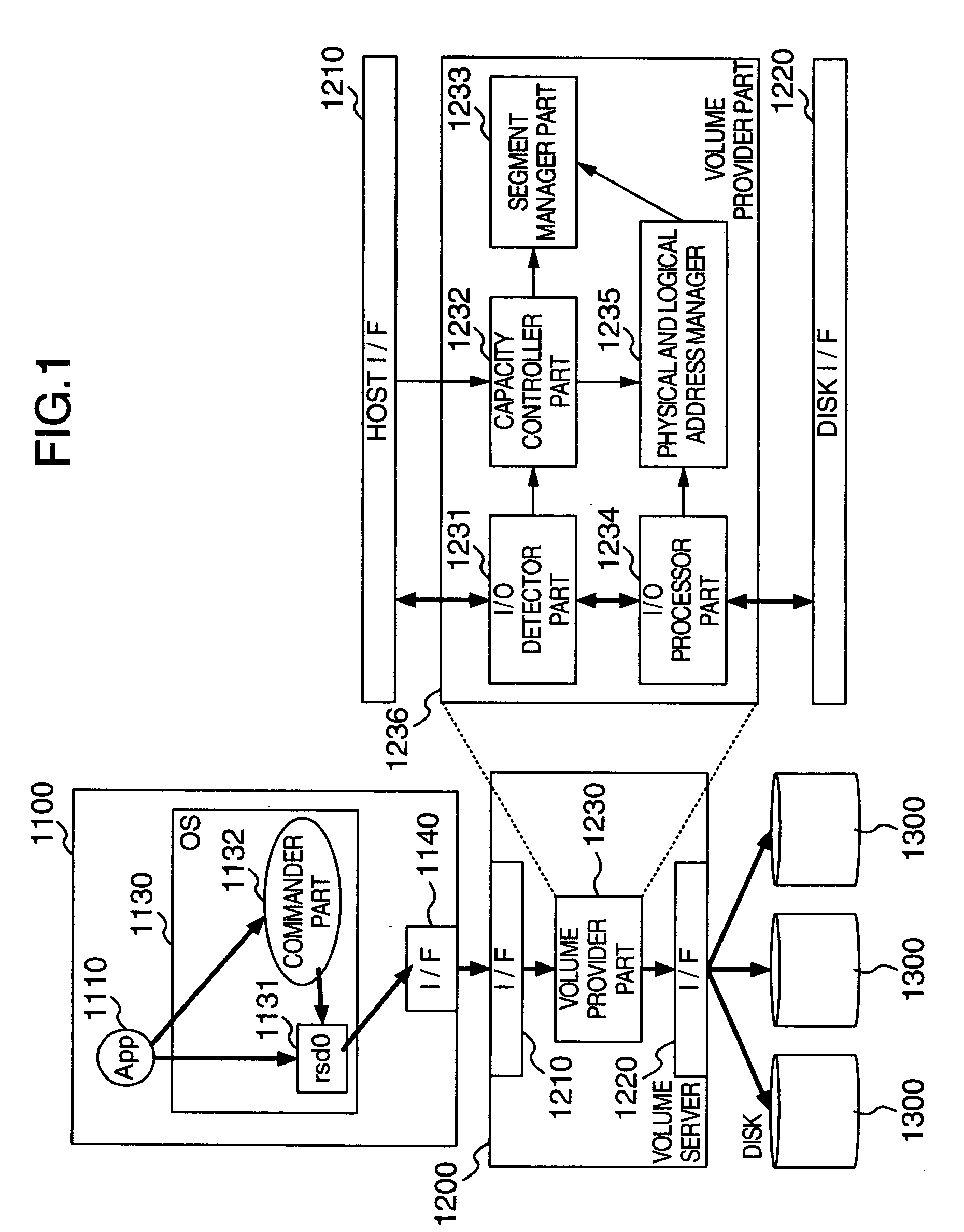
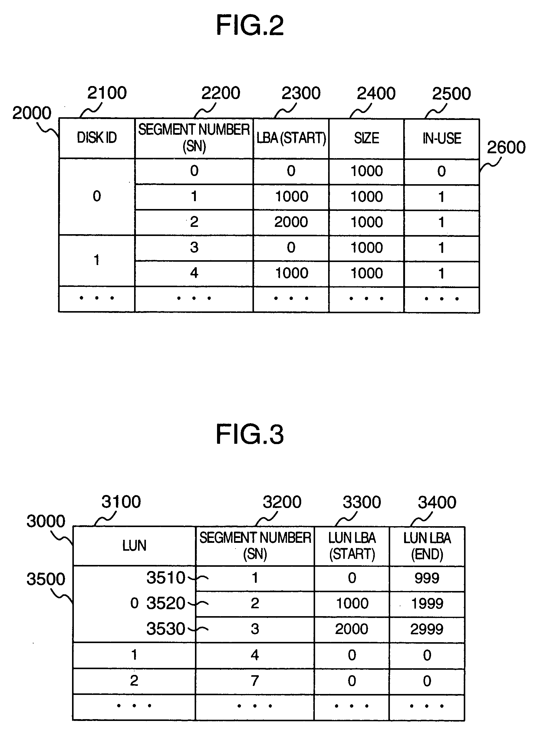
[0030] (1) First Embodiment

[0031] FIG. 1 shows a configuration m system includes a plurality of hosts 1100, a volume server 1200, and a plurality of magnetic disk device 1300. In this embodiment a single host 1100 and three magnetic disk devices are used, but only one magnetic disc device or any numbers of devices 1300 may be used instead. Moreover, the host 1100, the volume server 1200, and the magnetic disk devices 1300 have CPU, memory, and the like but they are not direction relationship with explanation of the embodiment of the present invention and their explanations are omitted.

[0032] The host 1100 has an application program (App) 1110, an operating system (hereinafter, referred to as OS) 1130, and a channel interface 1140. The application 1110 is application software such as a DB and a file system for reading and writing from / to a volume provided from the volume server 1200 as the volume providing device. The operating system 1130 includes a volume device part (rsd0) 1131 fo...

second embodiment

[0065] (2) Second Embodiment

[0066] In the first embodiment, when a write I / O access occurs to other than a storage domain of a logical volume provided from the volume server 1300 to the host 1100, the volume server 1200 successively allocates a storage domain, thereby performing a storage domain expansion to the logical volume provided by the volume server 1200. In the second embodiment, according to an instruction of the application 1110, a storage capacity expansion of a logical volume is performed in advance via the commander part 1132 of the host 1100 and the storage capacity of the logical volume is recognized by the OS 1130 before becoming usable by the application 1110. This procedure will be explained by referring to FIG. 18.

[0067] Firstly, the commander part 1132 of the host 1100 receives a storage domain expansion request by mLBA from the application 1110 (step 18001). The commander part 1132 of the host 1100 issues a write I / O to the LBA as a total of the entire logical v...


PUM


Abstract

A volume provider unit in a computer system that detects a logical block address of a read or write I / O accessing a logical volume of a storage device from a host. According to the logical block address fetched, a storage domain of the logical volume is dynamically expanded. Moreover, the storage domain of the logical volume is reduced or expanded according to an instruction of logical volume capacity reduction or expansion from a host commander part to a volume server.

Description

[0001] 1. Field of the Invention[0002] The present invention relates to a method for successive capacity expansion during on-line operation in a storage device system.[0003] 2. Description of the Related Art[0004] Recently, storage domains of a plurality of host computers are often stored in a single storage device. This tendency is promoted by, for example, a disk array. The disk array provides redundancy of the storage domains by a plurality of magnetic disk devices in a system, thereby increasing reliability and providing a necessary storage domain as a logical volume to a plurality of hosts. One of the merits of using this disk array is capacity expansion of the logical volume.[0005] For example, when a computer has used up a logical volume provided by a disk array, a free space in the disk array is cut out with an arbitrary length to be allocated as a logical volume, so that the computer can connect this logical volume to a logical volume in use, thereby expanding the storage d...

Claims


Application Information

Patent Timeline
Patent Type & Authority Applications(United States)
IPC IPC(8): G06F12/00G06F3/06G06F12/08
CPCG06F3/0605G06F3/0608G06F3/0689G06F3/0665G06F3/0644
Inventor KANO, YOSHIKIKITAMURA, MANABUARAI, KOUJI
Owner HITACHI LTD
Learn More