Robot vac with retractable power cord

Inactive Publication Date: 2004-10-14
THE SHARPER IMAGE
View PDF99 Cites 169 Cited by
  • Summary
  • Abstract
  • Description
  • Claims
  • Application Information

AI Technical Summary

Problems solved by technology

Since robot vacuums are typically powered by a battery, the cleaning units on the robot vacuums may not be strong enough to adequately clean a room.
Becaus

Method used


Image

  • Robot vac with retractable power cord
  • Robot vac with retractable power cord
  • Robot vac with retractable power cord

Examples


Embodiment Construction

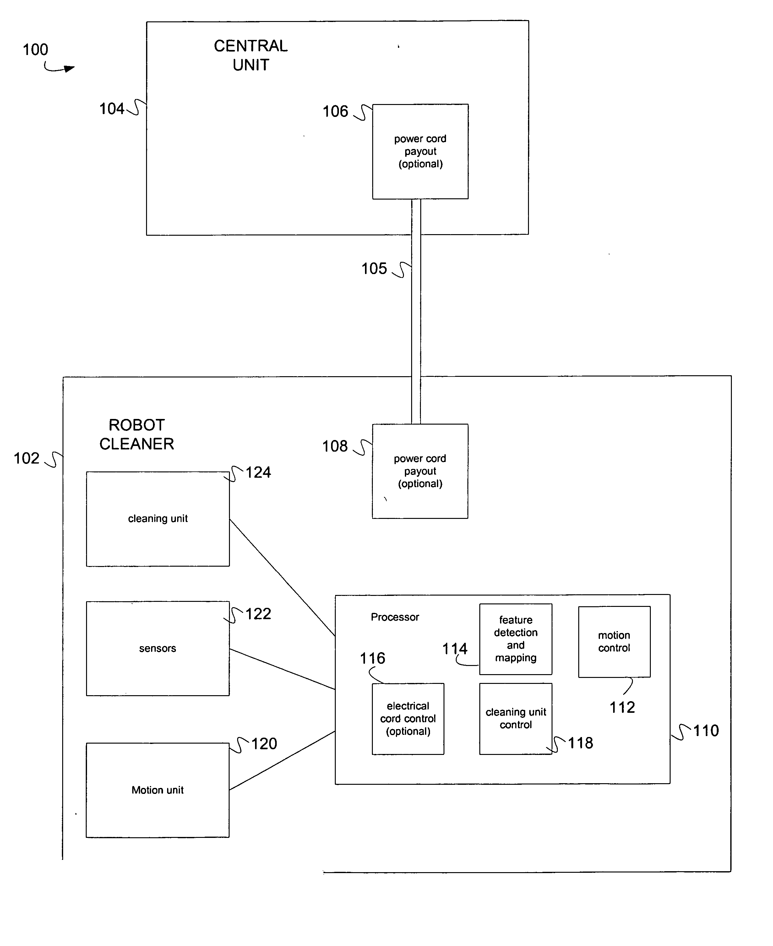
[0009] FIG. 1 illustrates a robot system 100. The robot system 100 includes a robot cleaner 102 and a unit 104, such as central unit. The robot cleaner 102 includes a cleaning unit 124 and a motion unit 120. The cleaning unit 124 can be any cleaning unit including a sweeping unit, waxing unit or a vacuum unit. The unit 104 is connected to the robot cleaner by electrical cord 105 to provide power to the robot cleaner 102. The robot cleaner can circle the unit to clean the room. The power cord can be wound in as the robot cleaner comes closer to the unit and can be wound out as the robot moves away from the unit.

[0010] In one embodiment, a power cord payout 106 is located at the unit 104. In another embodiment, the power cord payout 108 is located at the robot cleaner. The power cord payout can roll out the electrical cord 105. In one embodiment, the power cord payout maintains some level of tension on the electrical cord 105.

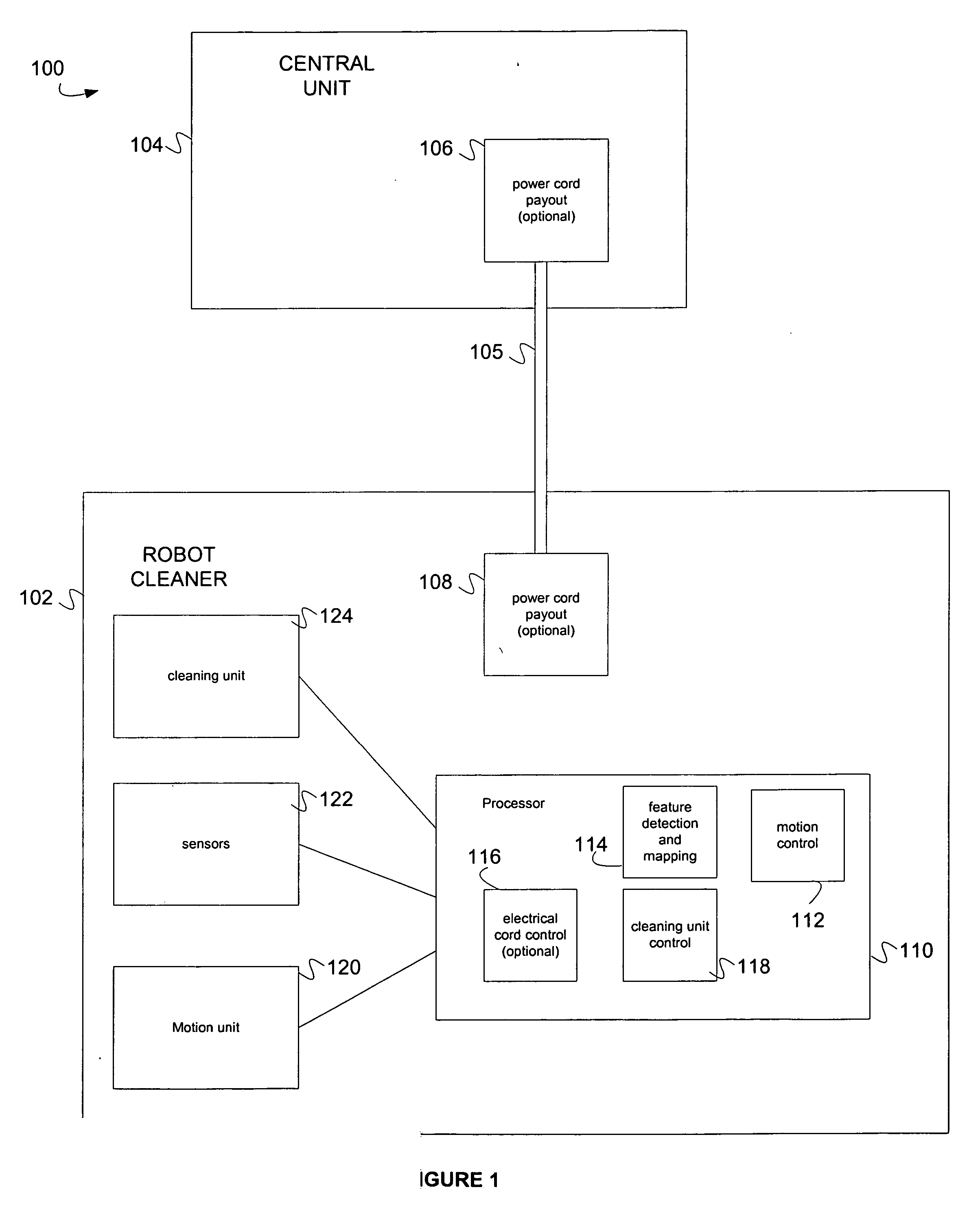
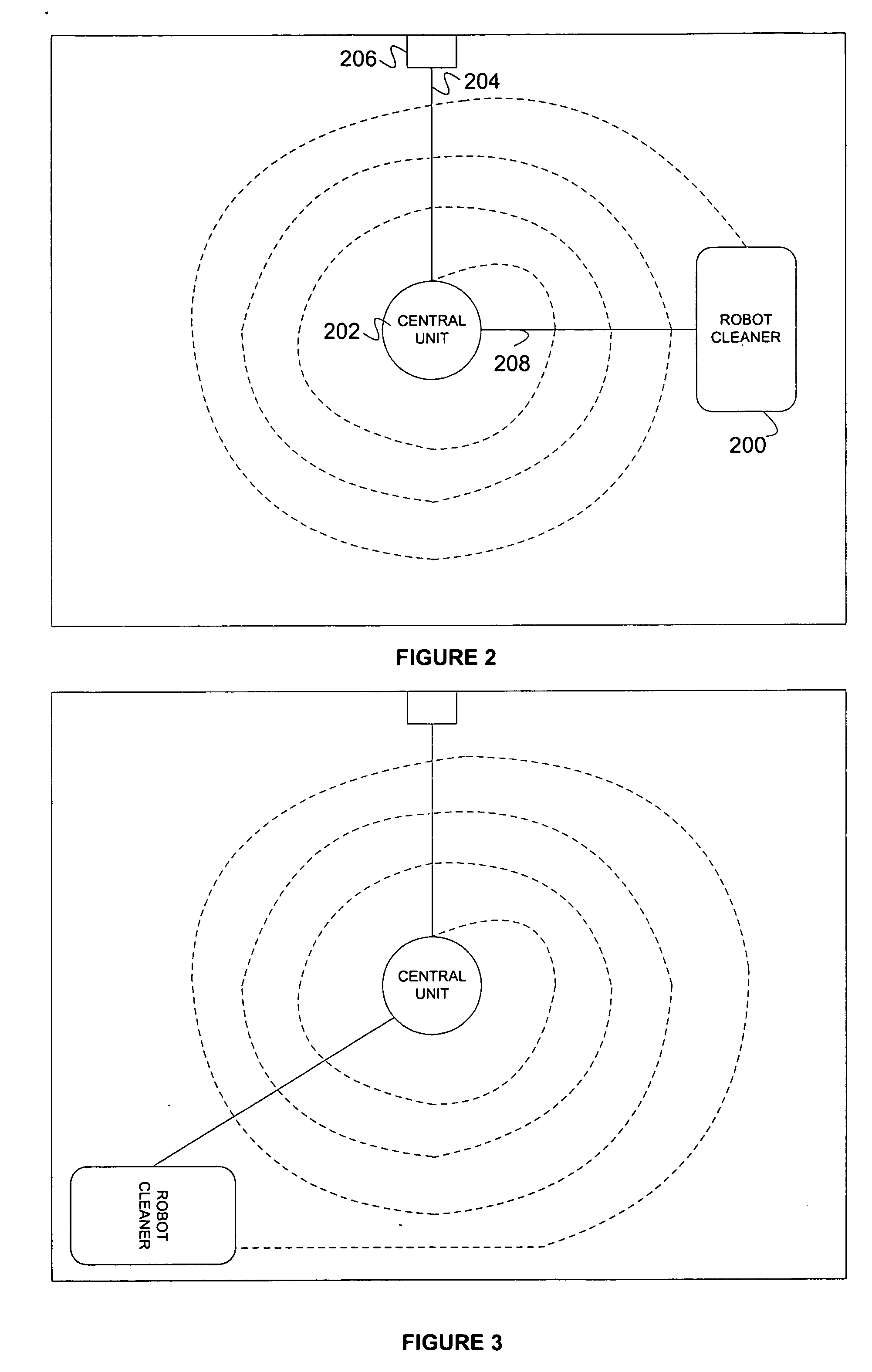
[0011] FIG. 2 illustrates an embodiment which the robot cle...


PUM


Abstract

A robot cleaning system uses a robot cleaner and a unit. The unit is connected to power the robot cleaner by a power cord. The robot cleaner can move around a room while being powered by the unit. In one embodiment, the unit is connected to a power socket by another power cord.

Description

CLAIM OF PRIORITY[0001] This application claims priority to U.S. Provisional Application No. 60 / 454,934 filed Mar. 14, 2003; U.S. Provisional Application No. 60 / 518,756 filed Nov. 10, 2003; U.S. Provisional Application No. 60 / 518,763 filed Nov. 10, 2003; U.S. Provisional Application No. 60 / 526,868 filed Dec. 4, 2003; U.S. Provisional Application No. 60 / 527,021 filed Dec. 4, 2003; U.S. Provisional Application No. 60 / 526,805 filed Dec. 4, 2003 and this application incorporates by reference U.S. Application No. ______ entitled "Robot Vacuum" By Taylor et al., filed Concurrently. (Attorney Docket No. SHPR-01360USS)FIELD OF THE INVENTION[0002] The present invention relates to a robot vacuums.BACKGROUND[0003] Robot vacuums are new and growingly popular way to clean rooms. An example of a robot vacuum is the Roomba Vacuum for the iRobot Company. Since robot vacuums are typically powered by a battery, the cleaning units on the robot vacuums may not be strong enough to adequately clean a roo...

Claims


Application Information

Patent Timeline
IPC IPC(8): B08B5/04B08B7/04
CPCA47L9/26A47L9/2831A47L9/2852A47L9/2868A47L9/2889B65H75/42B65H75/4484G05D1/0219G05D1/0274A47L2201/00A47L2201/04B65H2701/34G05D2201/0203
Inventor TAYLOR, CHARLES E.PARKER, ANDREW J.FAI LAU, SHEKBLAIR, ERIC C.HENINGER, ANDREWNG, ERIC
Owner THE SHARPER IMAGE
Why Eureka
Try Eureka