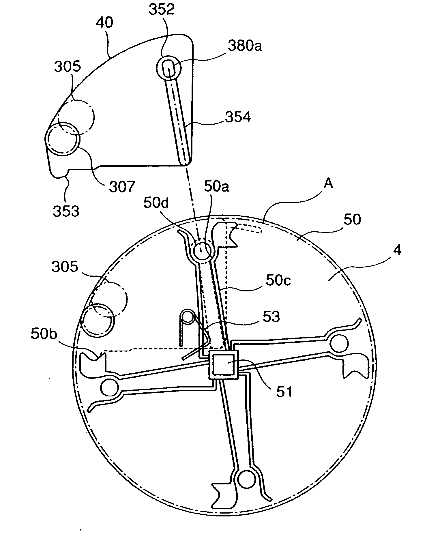
Cartridge and electrophotographic image forming apparatus
a technology of electrophotographic image and forming apparatus, which is applied in the direction of electrographic process apparatus, instruments, optics, etc., can solve the problems of reducing stiffness, affecting the appearance of the apparatus, so as to achieve smooth mounting
- Summary
- Abstract
- Description
- Claims
- Application Information
AI Technical Summary
Benefits of technology
Problems solved by technology
Method used
Image
Examples
embodiment 1
[0031] (Embodiment 1)
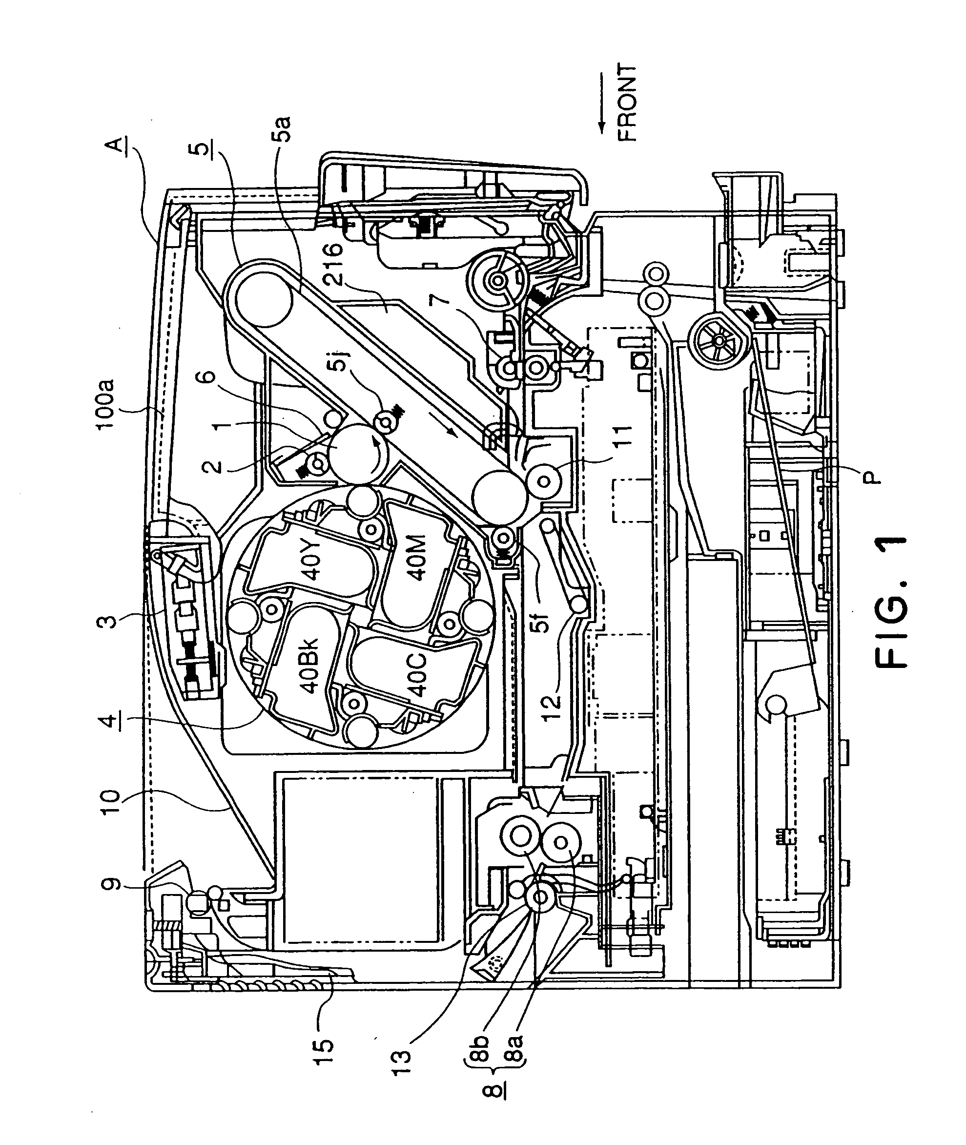
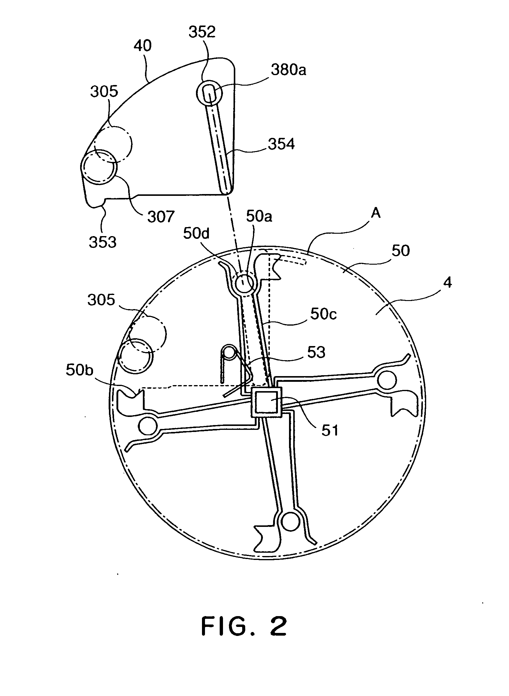
[0032] A development cartridge in accordance with the present invention, and an electrophotographic image forming apparatus compatible with such a development cartridge, will be described with reference to the appended drawings. In the following description of the preferred embodiments of the present invention, the front side means the upstream side in terms of the direction in which a recording medium is conveyed from the transfer station to fixation station (right side in FIG. 1). The left or right side of the apparatus main assembly or cartridge means the left or right side as seen from the front side of the apparatus. Further, the lengthwise direction means the direction which is parallel to the surface of a recording medium, and perpendicular (virtually perpendicular) to the direction in which the recording medium is conveyed.
[0033] (General Structure of Image Forming Apparatus)
[0034] First, referring to FIG. 1, the general structure of an electrophotogra...
embodiment 2
[0079] (Embodiment 2)
[0080] Next, referring to FIG. 13, the second embodiment of a development cartridge and an image forming apparatus, in accordance with the present invention will be described. FIG. 13 is a sectional view of a combination of the rotary 4 and development cartridge 40 in the second embodiment of the present invention, at a plane parallel to the front panel of an image forming apparatus, for showing how the development cartridge 40 is mounted into the rotary 4. The portions of the development cartridge 40 and rotary 4 in this embodiment similar to those in the first embodiment will be given the same referential codes as the referential codes given to the corresponding components in the first embodiment, and their descriptions will be omitted here.
[0081] In the above described first embodiment, the handgrip portion 381a (381b) and sliding member 380f (380g) were discrete, and were connected to each other. However, that structural arrangement is not intended to limit...
embodiment 3
[0084] (Embodiment 3)
[0085] Next, referring to FIGS. 14 and 15, the third embodiment of the development cartridge and image forming apparatus in accordance with the present invention will be described. FIG. 14 is a perspective view of the development cartridge 40 and rotary 4, in this embodiment of the present invention, as seen from the rear side, for depicting the mounting of the development cartridge 40 into the rotary 4. FIG. 15 is a schematic sectional view of the development cartridge 40. The portions of the development cartridge 40 and rotary 4 in this embodiment similar to those in the first embodiment will be given the same referential codes as the referential codes given to the corresponding components in the first embodiment, and their descriptions will be omitted here.
[0086] In the first and second embodiments, the structure in which the locking portions 380a, as a means for preventing the movement of the development cartridge 40, projecting from the lengthwise ends of ...
PUM
 Abstract
Description
Claims
Application Information
 - R&D
- Intellectual Property
- Life Sciences
- Materials
- Tech Scout
- Unparalleled Data Quality
- Higher Quality Content
- 60% Fewer Hallucinations
Browse by: Latest US Patents, China's latest patents, Technical Efficacy Thesaurus, Application Domain, Technology Topic, Popular Technical Reports.
© 2025 PatSnap. All rights reserved.Legal|Privacy policy|Modern Slavery Act Transparency Statement|Sitemap|About US| Contact US: help@patsnap.com


