Cartridge and electrophotographic image forming apparatus

a technology of electrophotographic image and forming apparatus, which is applied in the direction of electrographic process apparatus, instruments, optics, etc., can solve the problems of cartridge falling out of the rotary device, affecting the appearance of the apparatus, so as to achieve smooth mounting

Inactive Publication Date: 2005-11-01
CANON KK
View PDF33 Cites 102 Cited by
  • Summary
  • Abstract
  • Description
  • Claims
  • Application Information

AI Technical Summary

Benefits of technology

[0008]The primary object of the present invention is to provide a combination of a cartridge and an electrophotographic image forming apparatus, in which the cartridge can be more efficiently mounted into, or dismounted from, the main assembly of an image forming apparatus.
[0009]Another object of the present invention is to provide a combination of a cartridge and an electrophotographic image forming apparatus, in which the cartridge does not become unexpectedly dislodged from the main assembly of an image forming apparatus after the mounting of the cartridge into the apparatus main assembly.
[0010]Another object of the present invention is to provide a combination of a cartridge and an electrophotographic image forming apparatus, which ensures that the cartridge is placed in a predetermined position in the main assembly of an image forming apparatus as the cartridge is mounted into the image forming apparatus main assembly, and that cartridge remains in the predetermined position after the mounting.
[0011]Another object of the present invention is to provide a combination of a cartridge and an electrophotographic image forming apparatus, in which the cartridge does not become unexpectedly dislodged from a rotary device as the rotary device is rotated after the mounting of the cartridge into the rotary device, that is, a part of the image forming apparatus main assembly.
[0014]Another object of the present invention is to provide a combination of a cartridge and an electrophotographic image forming apparatus, in which the mounting or dismounting of the cartridge is instinctively understandable to an operator, and the cartridge is smoothly mountable into, or dismountable from, the main assembly of the image forming apparatus.

Problems solved by technology

Further, when mounting or dismounting a cartridge, the left and right springs are likely to become disengaged non-simultaneously from the cartridge, making it possible that the cartridge will become tilted and hang up in the rotary device.
On the other hand, reducing the stiffness of the spring to reduce the cartridge retaining force of the spring makes it possible for a cartridge to fall out of the rotary device and damage the apparatus main assembly.

Method used


Image

  • Cartridge and electrophotographic image forming apparatus
  • Cartridge and electrophotographic image forming apparatus
  • Cartridge and electrophotographic image forming apparatus

Examples


embodiment 1

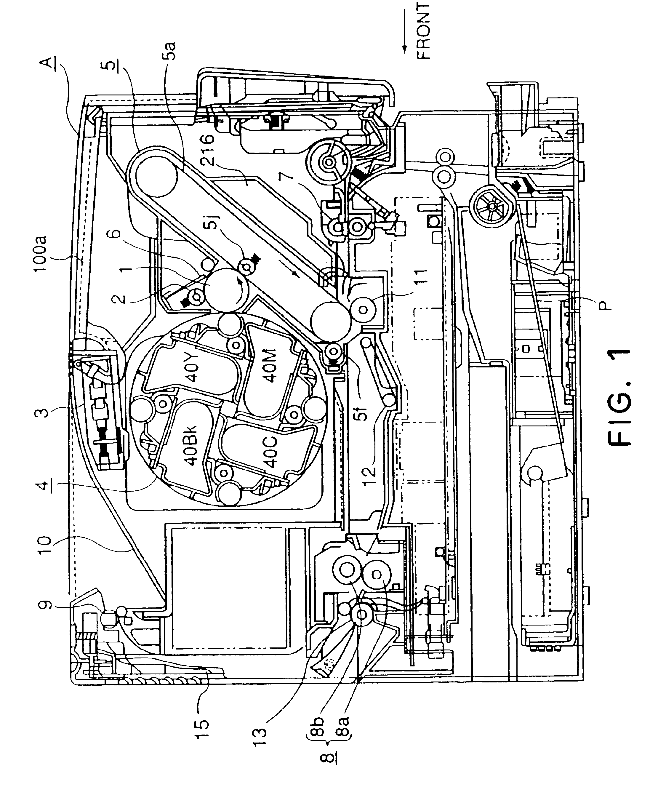
[0032]A development cartridge in accordance with the present invention, and an electrophotographic image forming apparatus compatible with such a development cartridge, will be described with reference to the appended drawings. In the following description of the preferred embodiments of the present invention, the front side is the upstream side in terms of the direction in which a recording medium is conveyed from the transfer station to the fixation station (right side in FIG. 1). The left or right side of the apparatus main assembly or cartridge is the left or right side as seen from the front side of the apparatus. Further, the lengthwise direction is the direction which is parallel to the surface of a recording medium, and perpendicular (virtually perpendicular) to the direction in which the recording medium is conveyed.

(General Structure of Image Forming Apparatus)

[0033]First, referring to FIG. 1, the general structure of an electrophotographic color image forming apparatus wi...

embodiment 2

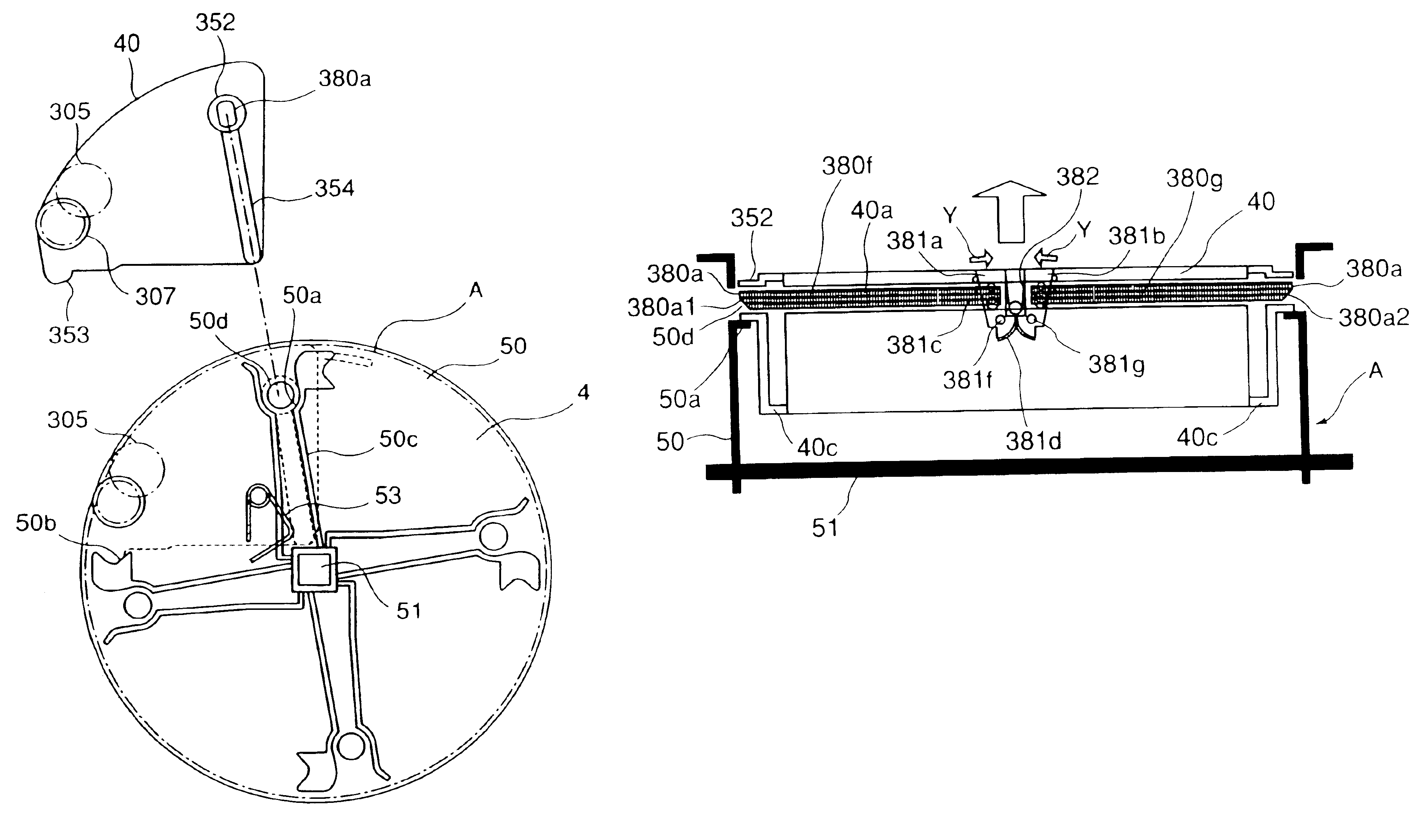
[0072]Next, referring to FIG. 13, the second embodiment of a development cartridge and an image forming apparatus, in accordance with the present invention will be described. FIG. 13 is a sectional view of a combination of the rotary device 4 and development cartridge 40 in the second embodiment of the present invention, at a plane parallel to the front panel of an image forming apparatus, for showing how the development cartridge 40 is mounted into the rotary device 4. The portions of the development cartridge 40 and rotary device 4 in this embodiment similar to those in the first embodiment will be given the same reference codes as the reference codes given to the corresponding components in the first embodiment, and their descriptions will be omitted here.

[0073]In the above described first embodiment, the handgrip portion 381a (381b) and sliding portion 380f (380g) were discrete, and were connected to each other. However, that structural arrangement is not intended to limit the s...

embodiment 3

[0076]Next, referring to FIGS. 14 and 15, the third embodiment of the development cartridge and the image forming apparatus in accordance with the present invention will be described. FIG. 14 is a perspective view of the development cartridge 40 and rotary device 4, in this embodiment of the present invention, as seen from the rear side, for depicting the mounting of the development cartridge 40 into the rotary device 4. FIG. 15 is a schematic sectional view of the development cartridge 40. The portions of the development cartridge 40 and rotary device 4 in this embodiment similar to those in the first embodiment will be given the same reference codes as the reference codes given to the corresponding components in the first embodiment, and their descriptions will be omitted here.

[0077]In the first and second embodiments, the structure in which the locking portions 380a, as a means for preventing the movement of the development cartridge 40, projecting from the lengthwise ends of the...


PUM


Abstract

A cartridge removably mountable to a main assembly of an electrophotographic image forming apparatus includes a developing member, a developer accommodating portion, a locking portion to engage a locking portion of the main assembly of the apparatus to prevent the cartridge from disengaging from the main assembly after mounting of the cartridge, a grip to be gripped by an operator when the cartridge is mounted to the main assembly, and a releasing portion to move the locking portion of the cartridge in interrelation with a movement of the grip which is moved when the operator grips the grip to disengage the cartridge from the main assembly of the apparatus. The locking between the locking portion of the cartridge and the locking portion of the main assembly is released by the movement of the locking portion of the cartridge.

Description

CROSS-REFERENCE TO RELATED APPLICATION[0001]This application is a divisional of U.S. application Ser. No. 10 / 179,847, filed Jun. 26, 2002, now U.S. Pat. No. 6,834,173, the entire disclosure of which is hereby incorporated by reference.BACKGROUND OF THE INVENTIONField of the Invention and Related Art[0002]The present invention relates to a cartridge, and an electrophotographic image forming apparatus employing a cartridge.[0003]Here, an electrophotographic image forming apparatus is an apparatus for forming an image on a recording medium (for example, a recording paper, an OHP sheet, and the like) with the use of an electrophotographic image forming method. It includes an electrophotographic copying machine, an electrophotographic printer (a laser printer, an LED printer, and the like), a facsimile apparatus, a word processor, and the like.[0004]A cartridge system has long been in use, according to which a developing member and a developer storage portion, for example, are integrated...

Claims


Application Information

Patent Timeline
Patent Type & Authority Patents(United States)
IPC IPC(8): G03G15/01G03G15/00
CPCG03G15/0152G03G21/1647G03G21/1676G03G15/0121G03G15/0173G03G2215/0177G03G2221/1654G03G15/00
Inventor YAMAGUCHI, KOJISHIRATORI, TATSUYAKANNO, KAZUHIKO
Owner CANON KK
Why Eureka
Try Eureka