Beaver control device for a culvert pipe

a technology for culvert pipes and beavers, which is applied in the direction of artificial water canals, insect catchers and killers, moving filter elements, etc. it can solve the problems of beavers not being able to construct ideal damns, devices that do not discourage beavers from building, and floods and washouts, so as to reduce the number of beavers. , the effect of reducing the number of beavers

Active Publication Date: 2008-10-28
FLEMING WALTER
View PDF4 Cites 5 Cited by
  • Summary
  • Abstract
  • Description
  • Claims
  • Application Information

AI Technical Summary

Benefits of technology

[0011]The present invention overcomes the shortcomings of the prior art by providing an apex portion that is arranged to selectively couple with a drainage pipe such as those found in a weeping tile drainage system. A retaining member is provided to ensure that the drainage pipe is held in place when connected to the beaver control device so that animals cannot dislodge the drainage pipe from the desired position in which it drains into the culvert pipe. The rods extending between the base and apex portions prevent beavers from approaching the end of the culvert pipe while allowing small debris to flow through the openings between them.
[0013]Preferably the base portion comprises mounting elements for connecting the generally conical screen to the end of the culvert pipe for motion between a lowered position in which said screen substantially blocks the end of the culvert pipe and a raised position in which said screen does not substantially block at least a portion of said end of said culvert pipe. The raised position allows for easier cleaning of the device to remove any build up of debris.
[0016]There may be provided an actuator for moving the generally conical screen between the lowered and raised positions. In this case, preferably the actuator comprises a flexible longitudinal member attached to the apex portion and extending toward the base portion such that pulling said longitudinal member away from the apex portion causes the generally conical screen to pivot about the end of the culvert pipe from the lowered position to the raised position. The use of such a flexible longitudinal member, like a rope or chain, allows the device to be easily raised and lowered for occasional cleaning.
[0017]The base and apex portions may comprise a plurality of base members and apex members respectively, each base member being connected to a respective apex member by respective ones of the plurality of rods. In this case, preferably adjacent base members are coupled together and adjacent apex members are coupled together. Preferably the adjacent members are detachably coupled by bolts at flanges provided at opposite ends of each member. This allows the device to be partially assembled on-site from multiple pieces which can be transported with less hassle and lower costs.

Problems solved by technology

Unfortunately, such pipes represent an ideal place for beavers to construct a damn and restrict the flow of water.
These damns can quickly cause flooding and washouts when water levels are elevated, for example, by heavy rains or melting snow.
Vertical screens or grates have been used to prevent beavers from entering culverts, but such devices do not discourage beavers from building dams at the ends of a culvert pipe.
Also, water flows tend to deposit debris at such barriers which builds up over time and restricts flow through the culvert.
The beavers cannot construct an ideal damn at the opening of the culvert as they cannot properly anchor the structure.
As a result of limiting access to the culvert by beavers, the prior art also limits access to the culvert pipe by others.
In addition, large culverts require correspondingly large screens that are difficult and costly to transport due to their dimensions.

Method used


Image

  • Beaver control device for a culvert pipe
  • Beaver control device for a culvert pipe
  • Beaver control device for a culvert pipe

Examples


first embodiment

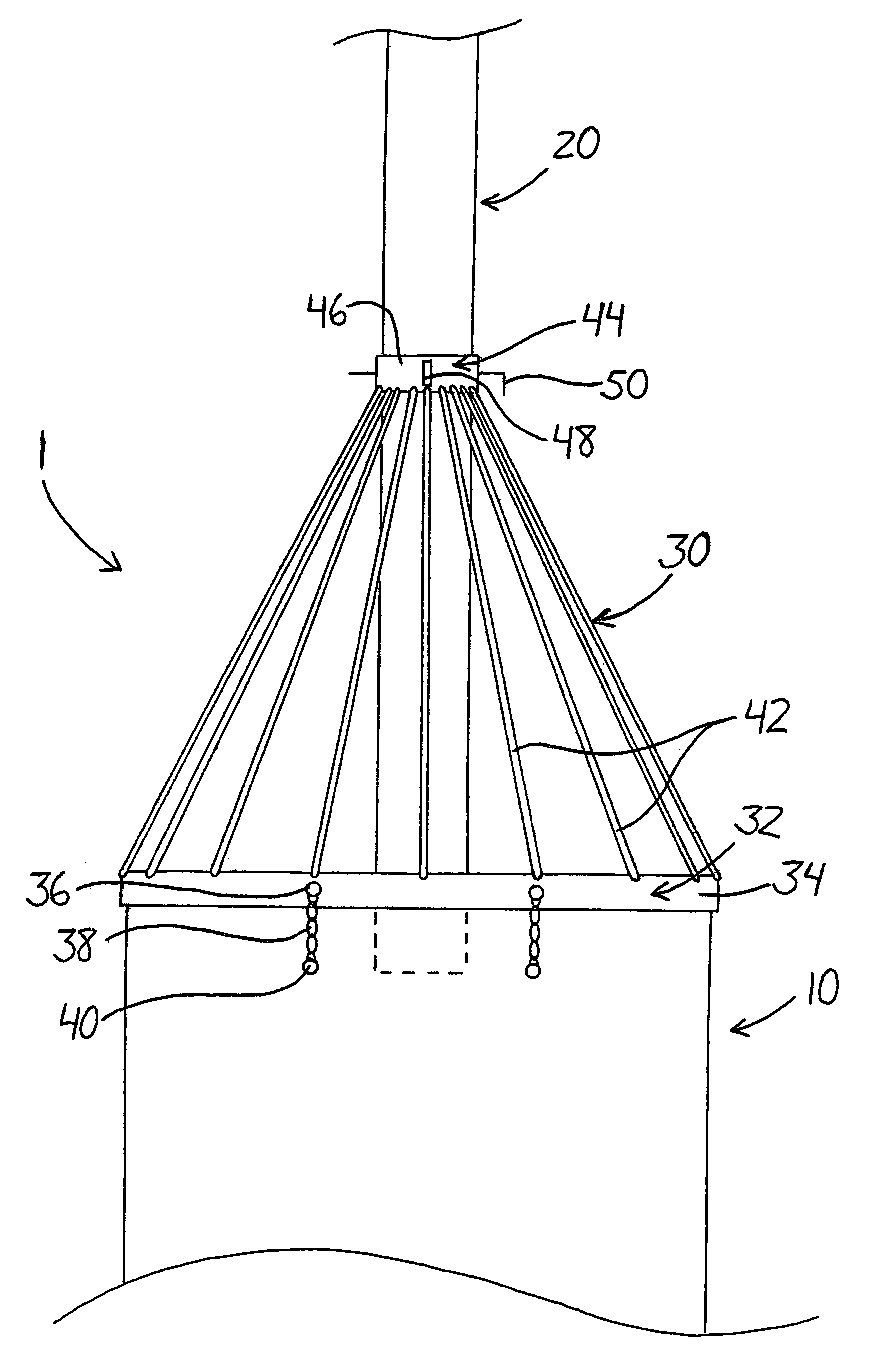
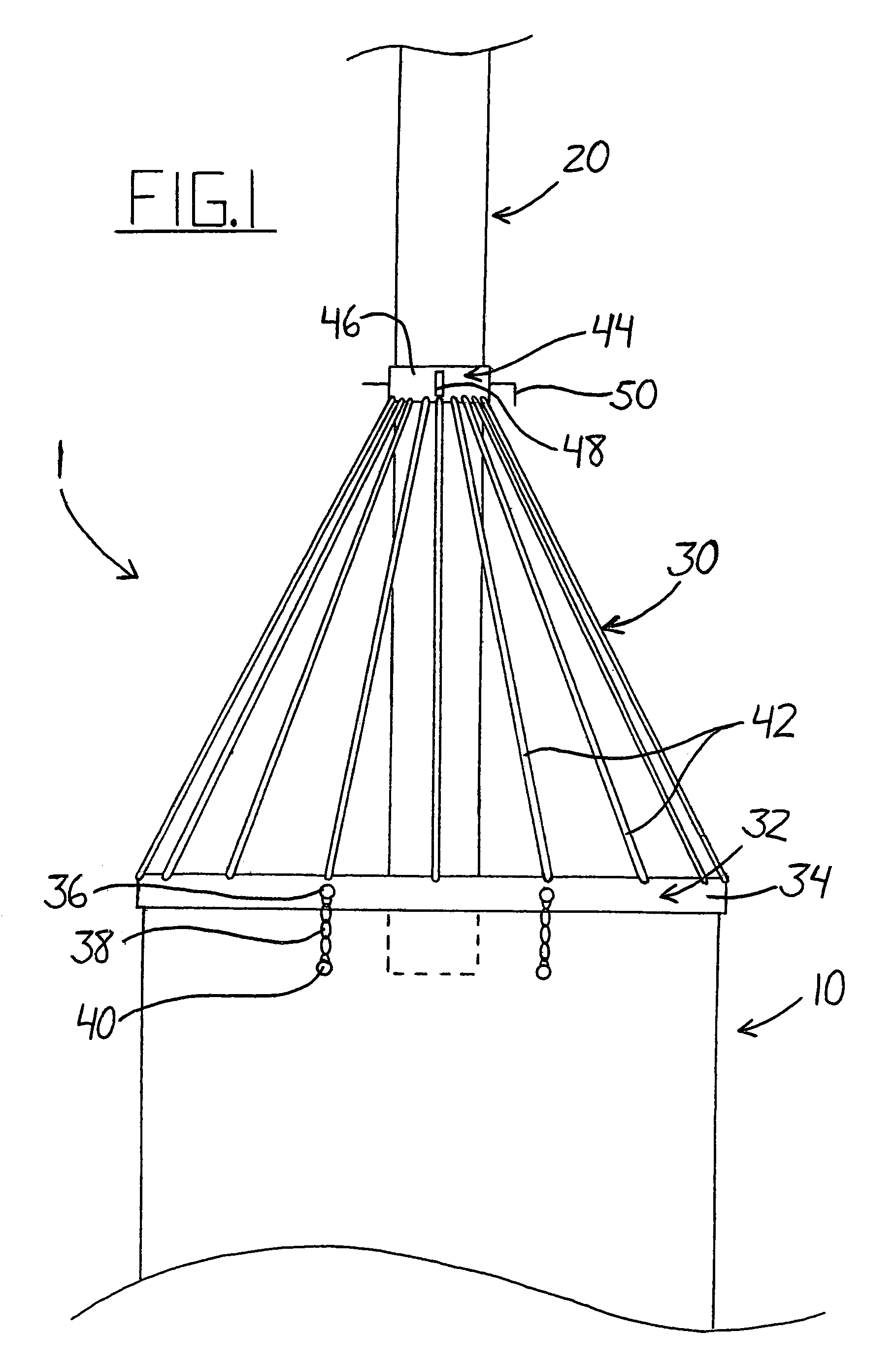
[0034]FIG. 1 illustrates the device 1 which is constructed to form a single structure that is installed without further assembly. The base portion 32 has a circular rim 34 which is dimensioned to fit over the end of the culvert pipe 10 such that the opening of the pipe 10 is not blocked in any way by the base portion 32. The base portion 32 is further connected to the culvert pipe 10 by means of two lengths of chain 38 spaced apart near the top of the device 1 and culvert 10. The chains 38 are attached to the base portion 32 by bolts 36 secured through the rim 32. Similarly, the chains 38 are attached to the culvert pipe 10 by means of bolts 40. The chains 38 ensure that the screen 30 remains secured to the culvert 10, but do allow limited motion of the device 1 with respect to the culvert, the purpose of which will be explained below. Similar to the base portion 32, the apex portion 44 has a circular rim 46 which is dimensioned to fit over the end of the weeping tile pipe 20 such t...

second embodiment

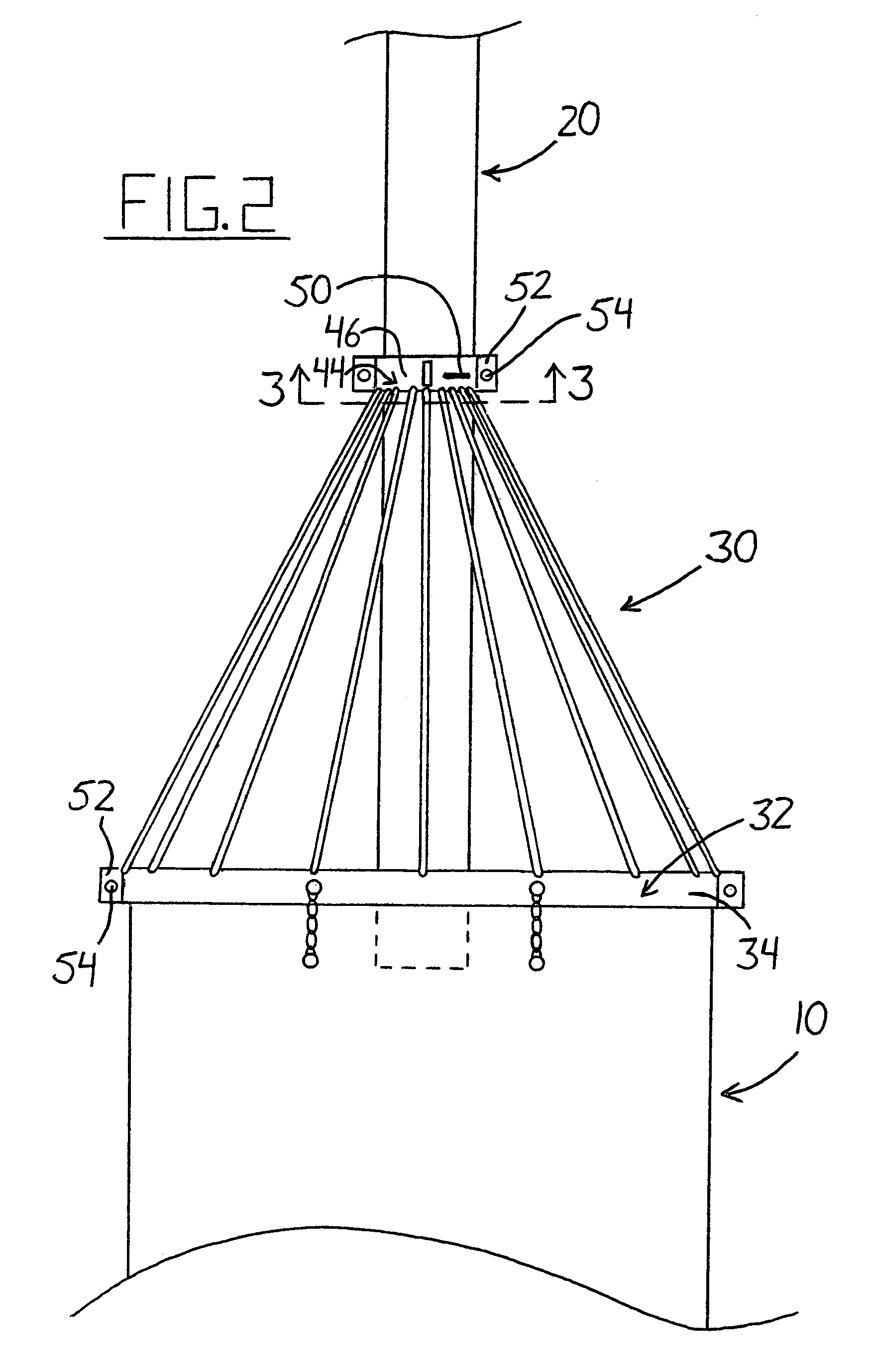
[0036]FIG. 2 illustrates the beaver control device 1 in which the screen 30 is made of two pieces which can be assembled on-site. This proves useful for larger applications requiring screens of significant dimensions that may be difficult and / or costly to transport. While having the same general structure as the embodiment of FIG. 1, the difference lies in the rims 34 and 46 of the base portion 32 and apex portion 44 respectively. Here the rims are each made of two semi-circular portions that are detachably coupled together by bolts 54 at flanges 52. FIG. 3 shows a cross section taken along line 3-3 of FIG. 2 near the apex portion 44 which illustrates the two piece construction more clearly. The apex rim 46 is made up of two semicircular apex members 45 and 47. A flange 52 is provided at each end of each member so that when the flanges 52 of members 45 and 47 are aligned, they fit together in a flush manner. The flanges 52 are connected by a bolt 54 and the apex members 45 and 47 co...


PUM

PropertyMeasurementUnit
lengthaaaaaaaaaa
movementaaaaaaaaaa
distanceaaaaaaaaaa

Abstract

A beaver control device for a culvert pipe features a generally conical screen having a base portion and an apex portion connected by a plurality of rods. The base portion has a rim sized to fit about the end of the culvert pipe. The apex portion has a rim with an opening sized to selectively receive a weeping tile or other drainage pipe. The screen prevents beavers from damming the culvert while allowing the drainage pipe to drain into or pass through the culvert. A pin is provided to either lock the drainage pipe in place or partially close off the opening in the apex portion when not in use. The screen is movable between raised and lowered positions to allow easy access to the screen and culvert. In one embodiment, the screen is constructed in multiple pieces to allow for easy transport and on-site assembly.

Description

[0001]This invention relates generally to a cone-shaped screen for attachment to an end of a culvert pipe for preventing beavers from building a dam to block the flow of water. More particularly, the present invention relates to a cone-shaped screen having an apex portion for selective connection to a drainage pipe arranged to drain into or pass through the culvert pipe.BACKGROUND OF THE INVENTION[0002]Culvert pipes are widely used to allow water to flow beneath roads without having to redirect it or construct a bridge to pass over the stream. Unfortunately, such pipes represent an ideal place for beavers to construct a damn and restrict the flow of water. These damns can quickly cause flooding and washouts when water levels are elevated, for example, by heavy rains or melting snow. Vertical screens or grates have been used to prevent beavers from entering culverts, but such devices do not discourage beavers from building dams at the ends of a culvert pipe. Also, water flows tend to...

Claims


Application Information

Patent Timeline
Patent Type & Authority Patents(United States)
IPC IPC(8): E03F7/06
CPCE03F7/06
Inventor FLEMING, WALTER
Owner FLEMING WALTER
Why Eureka
Try Eureka