Method and apparatus for forming a part with dampener

a technology of dampener and dampener body, which is applied in the direction of braking discs, foundry patterns, moulding apparatus, etc., can solve the problems of unwanted noise and vibration generated during the braking process, and achieve the effect of effective and efficient construction

Inactive Publication Date: 2005-01-20
FRENI BREMBO SPA
View PDF6 Cites 73 Cited by
  • Summary
  • Abstract
  • Description
  • Claims
  • Application Information

AI Technical Summary

Benefits of technology

[0010] In accordance with the present invention, it has been discovered that a damped part, such as a brake rotor, with a dampening structure can be inexpensively, effectively and efficiently constructed. Thus, the manufacturing step of adding a separate external dampening structure, as known in the prior art, is avoided.
[0011] It has also been discovered that with the dampening structure trapped within the part, the risk of a damaged or broken structure being ejected from the part or interfering with other working parts is reduced or prevented.

Problems solved by technology

A problem commonly associated with disk brakes is that unwanted noise and vibration are generated during the braking process.

Method used


Image

  • Method and apparatus for forming a part with dampener
  • Method and apparatus for forming a part with dampener
  • Method and apparatus for forming a part with dampener

Examples


Embodiment Construction

[0021] It is to be understood that the invention may assume various alternative orientations and step sequences, except where expressly specified to the contrary. It is also to be understood that the specific devices and processes illustrated in the attached drawings, and described in the following specification are simply exemplary embodiments of the inventive concepts defined in the appended claims. Hence, specific dimensions, directions or other physical characteristics relating to the embodiments disclosed are not to be considered as limiting, unless the claims expressly state otherwise.

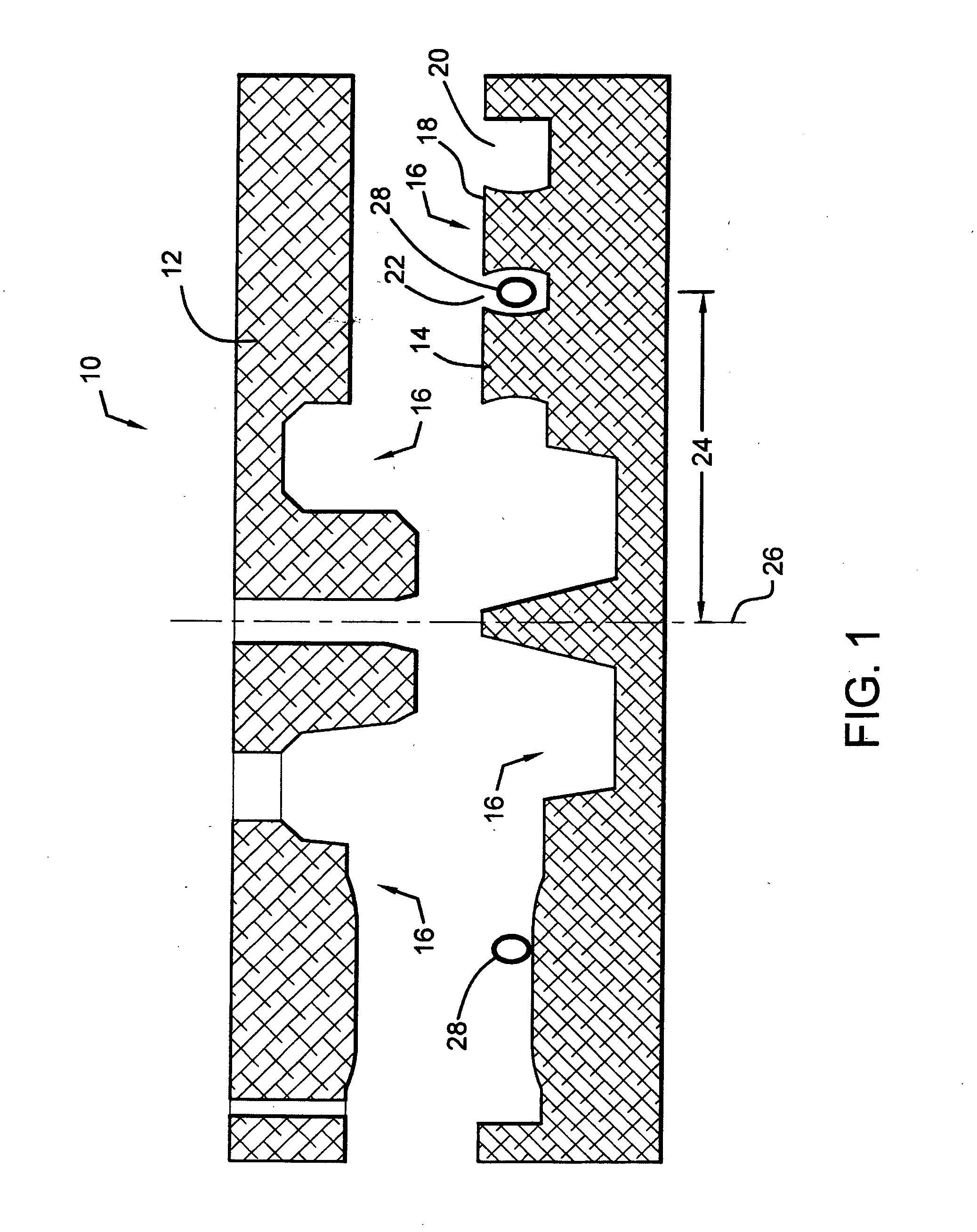
[0022] Referring now to FIG. 1, a sand core mold 10 is depicted as having a first portion 12 and at least a second portion 14. The individual portions 12, 14 may be constructed of one piece or they may be of a multi-piece construction. In this embodiment, the first portion 12 is located above the second portion 14, however, the portions 12, 14 may be located in any orientation, including vertica...


PUM

PropertyMeasurementUnit
geometric structuresaaaaaaaaaa
shapeaaaaaaaaaa
heat resistantaaaaaaaaaa

Abstract

A method for producing a damped part where a sand core is formed with at least one dampening structure with the sand core. The sand core with the at least one dampening structure therein is located in a mold. A part is cast from the mold and the sand core. The sand core is removed from the cast part leaving the at least one dampening structure in contact with the part.

Description

FIELD OF THE INVENTION [0001] The present invention relates to an apparatus and a method of forming a part with a dampener. More specifically, the invention relates to an apparatus and method of forming a brake component, such as a rotor, having a dampener. BACKGROUND OF THE INVENTION [0002] Automobiles, trucks, buses, off-road and construction vehicles, aircraft and light rail vehicles commonly use disk brakes. Disk brakes utilize a disk which turns with the wheel of the vehicle. When the brakes are applied, stationary pads are pressed against the rotor through hydraulic pressure by a brake caliper. The frictional forces between the brake pads and the rotor slow or bring the vehicle wheel to a stop. [0003] A problem commonly associated with disk brakes is that unwanted noise and vibration are generated during the braking process. Numerous attempts have been made to reduce, or prevent, the unwanted noise and vibration by adding separate components to the rotor after it has been cast...

Claims


Application Information

Patent Timeline
Patent Type & Authority Applications(United States)
IPC IPC(8): B22D19/12F16D65/00F16D65/12
CPCB22D19/12F16D2250/0007F16D65/12F16D65/0006
Inventor FRAIT, JOHNDUNN, MICHAELTEDESCO, MARCELLOSANDBERG, DANIEL
Owner FRENI BREMBO SPA
Why Eureka
Try Eureka