Downhole electrical submersible power generator

Inactive Publication Date: 2005-01-20
CONOCOPHILLIPS CO
View PDF15 Cites 51 Cited by
  • Summary
  • Abstract
  • Description
  • Claims
  • Application Information

AI Technical Summary

Benefits of technology

[0013] According to one aspect of one or more embodiments of the present invention, the present invention relates to a downhole submersible electrical power generator including a housing forming a fluid conduit; an inlet disposed on the housing; an outlet disposed on the housing, wherein the inlet and the outlet are adapted to allow a fluid to flow into and out of the housing, respectively, and wherein the fluid flows through the fluid conduit dependent on a naturally occurr

Problems solved by technology

In particular, a number of large machines used in hydrocarbon production (pumps, etc.) require large amounts of electrical power.
In particular, having to lay power lines may be problematic when the platform is offshore.
As hydrocarbon production facilities move further and further away from land, this problem continues to grow in importance.
In addition, equipment used in the wellbore often requires a downhole electric power source for various operations.
However, a significant problem with the use of batteries as a power supply in a downhole environment is their limited life expectancy.
The expected life of a battery is typically much shorter than in “standard” operating conditions due to harsh environmental factors.
Further, caustic chemicals and fluids can cause early batt

Method used


Image

  • Downhole electrical submersible power generator
  • Downhole electrical submersible power generator
  • Downhole electrical submersible power generator

Examples


Embodiment Construction

[0020] In the following detailed description of the invention, numerous specific details are set forth in order to provide a more thorough understanding of the invention. However, it will be apparent to one of ordinary skill in the art that the invention may be practiced without these specific details. In other instances, well-known features have not been described in detail to avoid obscuring the invention.

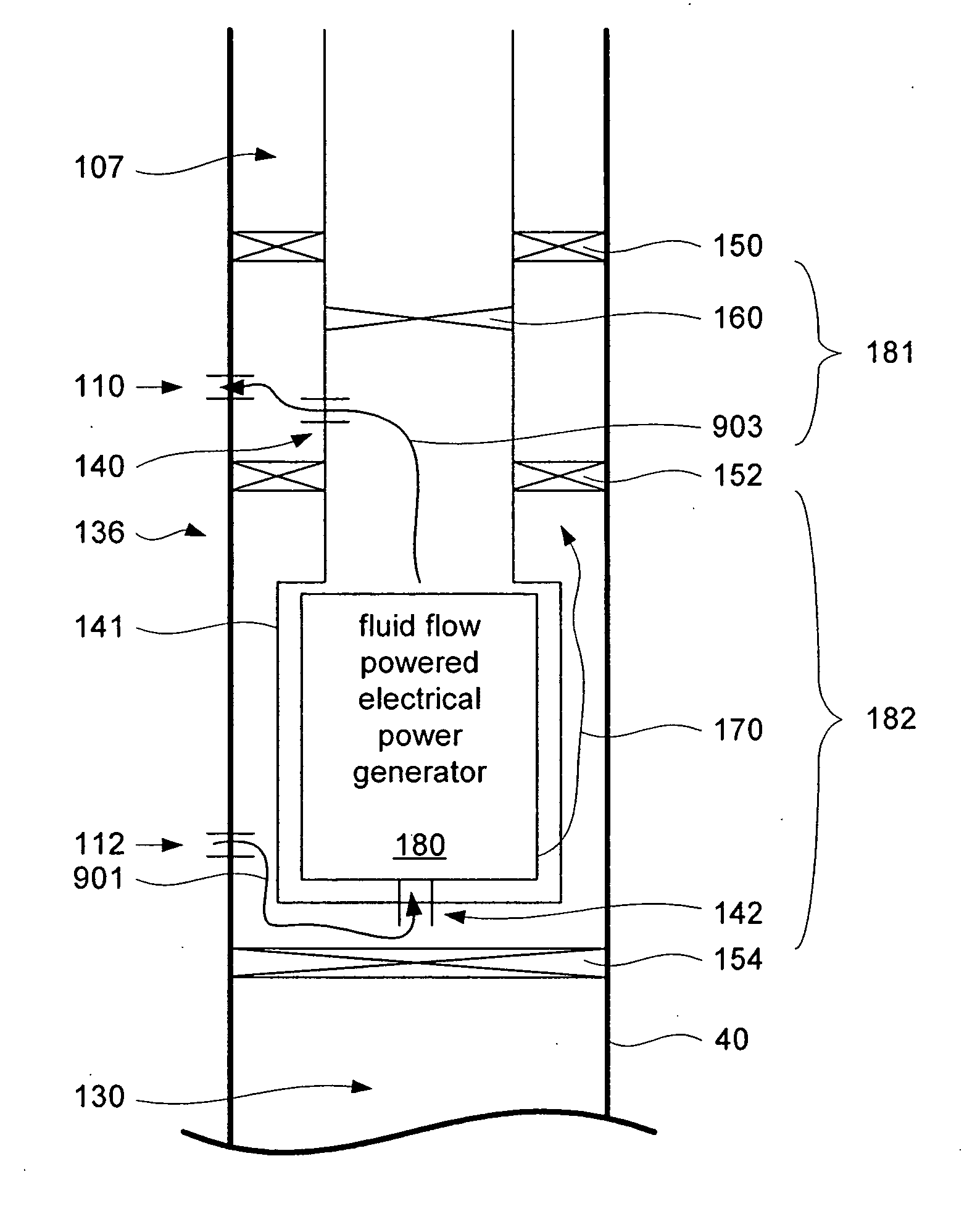
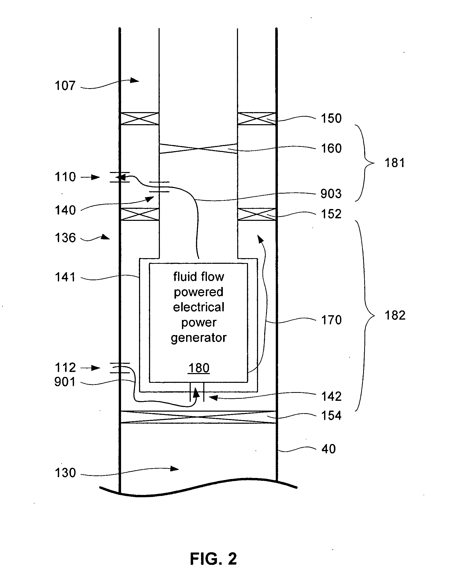
[0021] In one aspect, the present invention relates to a method and apparatus for providing large amounts of electrical power that involve a downhole submersible electrical power generator. Embodiments of the present invention may be used to provide ½ Megwatt of power or more to local equipment on a rig site, or may be connected to a power grid, where the energy may be sold for a profit.

[0022] In particular, embodiments of the present invention may find particular utility in applications in the Gulf of Mexico, where a number of “watered out” wells exist. As used herein, “watere...


PUM


Abstract

A method and apparatus is described for a downhole submersible electrical power generator. The electrical power generator includes a housing forming a fluid conduit. An inlet is disposed on the housing. Also, an outlet is disposed on the housing where the inlet and the outlet are adapted to allow a fluid to flow into and out of the housing, respectively. A fluid flow powered electrical power generator is disposed inside the housing and is adapted to generate electrical power from the fluid flowing through the housing. An isolation packer is disposed outside the housing between the inlet and the outlet where the isolation packer is adapted to isolate the inlet and the outlet in different zones in a wellbore.

Description

CROSS-REFERENCE TO RELATED APPLICATIONS [0001] This application claims priority, pursuant to 35 U.S.C. § 119(e), of U.S. Provisional Patent Application No. 60 / 487,494 filed Jul. 15, 2003. That Application is incorporated by reference in its entirety.BACKGROUND OF INVENTION [0002] Electrical power is an important commodity in nearly all aspects of life. One such area where electrical power is important is in the hydrocarbon production arena. In particular, a number of large machines used in hydrocarbon production (pumps, etc.) require large amounts of electrical power. In many situations it is advantageous to be able to provide power locally, rather than having to lay power lines over vast distances. In particular, having to lay power lines may be problematic when the platform is offshore. As hydrocarbon production facilities move further and further away from land, this problem continues to grow in importance. [0003] In addition, equipment used in the wellbore often requires a downh...

Claims


Application Information

Patent Timeline
IPC IPC(8): E21B41/00H02P6/14
CPCH02P6/142E21B41/0085H02P6/15
Inventor COUSINS, EDWARD THOMAS
Owner CONOCOPHILLIPS CO
Why Eureka
Try Eureka