
Compliant linear bearing

a technology of linear bearings and bearing guides, applied in the direction of elastic bearings, bearing rigid support, transportation and packaging, etc., can solve the problems of adding cost and complexity to the bearing design, or the cost of conventional linear bearings and guides is high, so as to prevent excessive radial motion

Inactive Publication Date: 2005-01-20
HONEYWELL INT INC
View PDF17 Cites 14 Cited by
  • Summary
  • Abstract
  • Description
  • Claims
  • Application Information

AI Technical Summary

Benefits of technology

The present invention provides a bearing that can withstand high radial loads and prevent damage from resonant vibration. The bearing includes a spring that provides a resilient force through the bearing pad onto a shaft. The bearing pad is made of multiple individual pads, and there are gaps between them to allow for variations in the shaft size. The bearing material is selected to provide a maximum linear resistance to axial motion. The bearing can be used to support a load along a shaft and is particularly useful in moving a ram air door. The invention also includes a method for cleaning the nut tube during movement.

Problems solved by technology

Conventional linear bearings and guides are either expensive, using precision roller or ball bearing supports, or are very inexpensive sleeve type bearings that are either slightly oversize to effect a clearance fit and dimensional variation, or are split to accommodate size variations in the mounting base.
The bearing of this patent relies on the use of a separate external housing to support the bearing body, adding cost and complexity to the bearing design.

Method used


Image

  • Compliant linear bearing
  • Compliant linear bearing
  • Compliant linear bearing

Examples


example 1

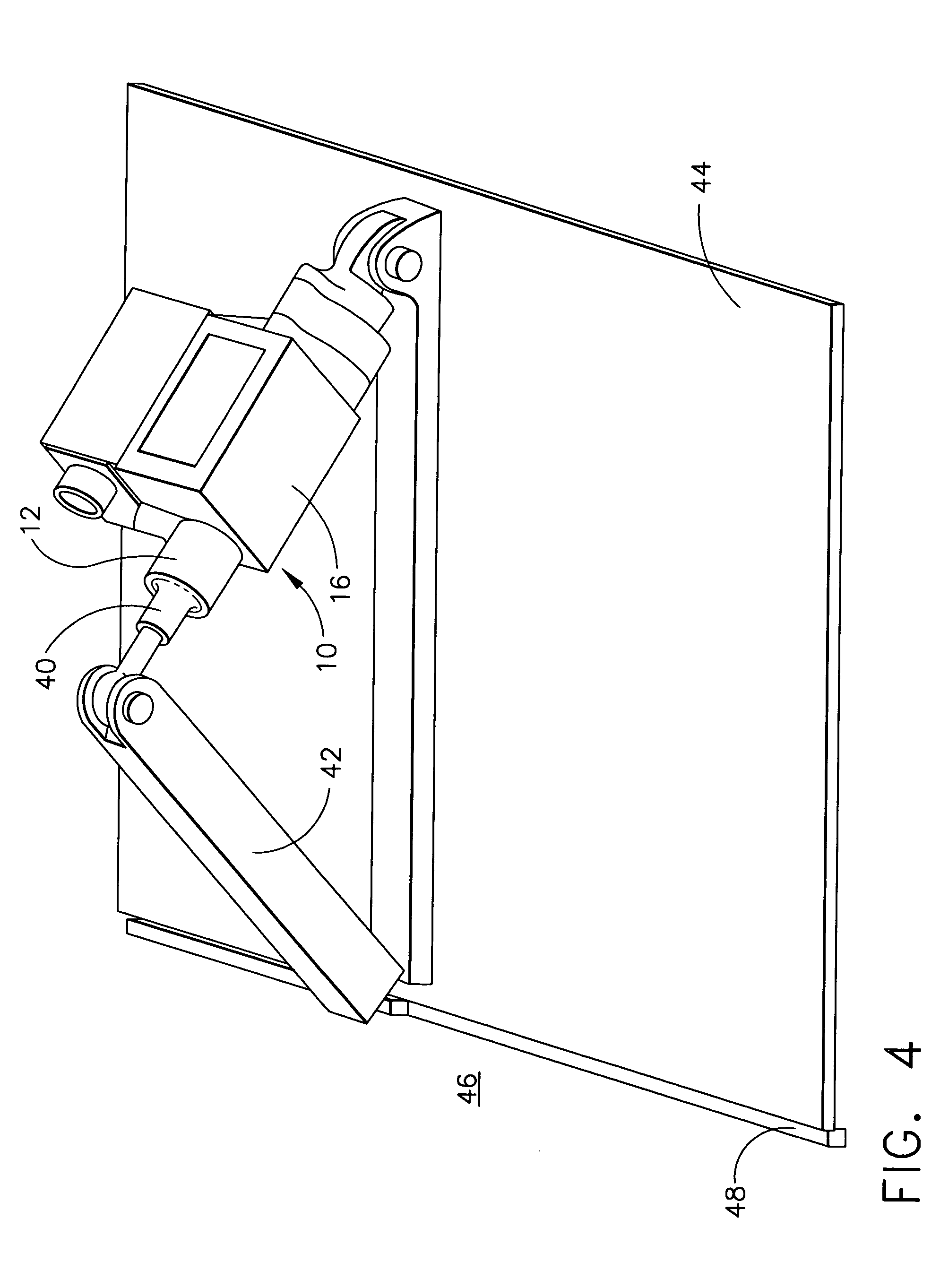
[0027] Referring to FIG. 4, a ram door 44 of an aircraft 46 may be attached to a shaft 12. A driven screw 40 (drive means not shown) moves shaft 12 in an axial direction within linear bearing 10. This movement causes ram door 44 to pivot at a hinge 48, allowing the opening and closing of ram door 44. Linear bearing 10 is mounted on a linear bearing support 42. Linear bearing 10 for movement of ram door 44 on aircraft 46 may be made to the following design configuration. The nut tube (shaft 12) for a conventional ram door actuator may be about 0.689±0.001 inch. The outer shell 16 of linear bearing 10 may be made with a length of 0.625±0.001 inch and a outside diameter of 0.878±0.001 inch.

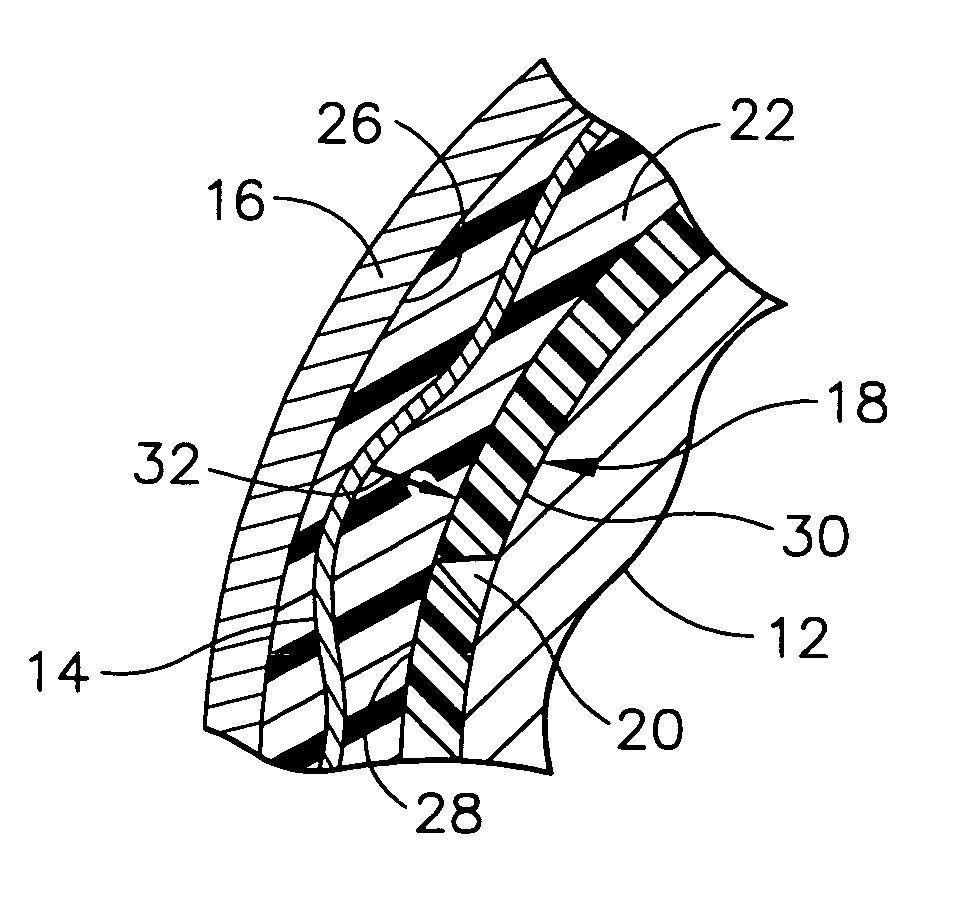
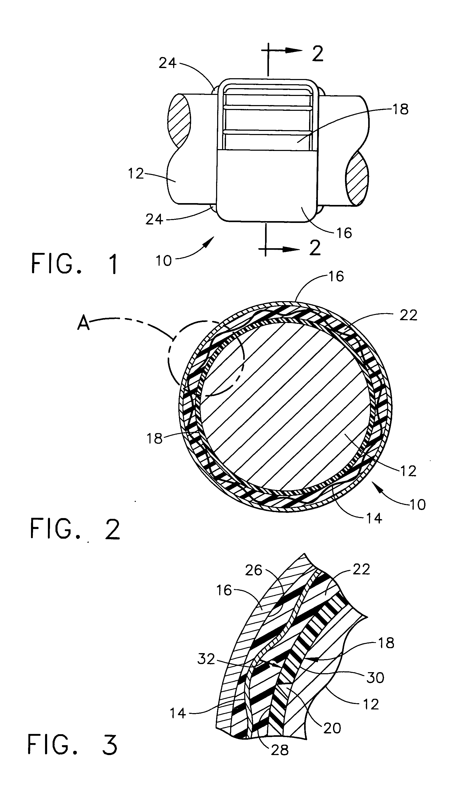
[0028] Referring now to FIGS. 2 through 4, spring 14 is molded into elastomeric base material 22 to give 4,000 to 5,000 pounds / inch radial spring rate as measured by deflection of shaft 12. Twelve bearing pads 18 are provided with triangular-shaped gaps 20 therebetween to give a bearing inside diame...


PUM


Abstract

A bearing outer shell encases a self-lubricating polymeric bearing pad material concentrically therein. A helical spring applies a force through from the outer shell, through the bearing pad material, and onto a shaft when the bearing is installed on a shaft. An elastomeric base material may be interposed between the outer shell and the bearing pad to provide additional resiliency. The shaft may be sized to create an interference fit, causing a radial preload that can be designed to exceed the expected external vibration or shock forces. Proper selection of the elastomeric base material affords damping of these environments. The bearing provides the necessary guidance with minimal loss in power consumption. Therefore, not only is the useful life of the shaft and housing extended, but the life of the associated gears, bearings, and components that require proper alignment to minimize wear the load concentrations is further extended.

Description

BACKGROUND OF THE INVENTION [0001] The present invention generally relates to a linear bearing for support of a sliding shaft or the like and, more specifically, to a compliant linear bearing having elastomeric and thermoplastic compounds and a helically wound wave spring to achieve the desired physical and functional properties. [0002] Most linear actuators require guidance and support of an output shaft or tube assembly as the free end moves a load from a fully retracted to a fully extended position. Conventional linear bearings and guides are either expensive, using precision roller or ball bearing supports, or are very inexpensive sleeve type bearings that are either slightly oversize to effect a clearance fit and dimensional variation, or are split to accommodate size variations in the mounting base. [0003] U.S. Pat. No. 4,799,653 discloses a shock and vibration control mechanism for radial attenuation of shock and vibration between two concentric rings, tubes or sleeves separa...

Claims


Application Information

Patent Timeline
Patent Type & Authority Applications(United States)
IPC IPC(8): B64C13/24F16C27/06F16C29/00F16C29/02
CPCB64C13/24F16C29/02F16C29/002F16C27/06F16C2326/43
Inventor MCDEARMON, ROBERT J.
Owner HONEYWELL INT INC
Learn More