

Stab proof vest
a vest and stab technology, applied in the field of stab proof vests, can solve the problems of side protection from being stabbed, protective gear is too heavy to wear for a long period of time,
- Summary
- Abstract
- Description
- Claims
- Application Information
AI Technical Summary
Benefits of technology
Problems solved by technology
Method used
Image

Examples
first embodiment
[0048] (First Embodiment)
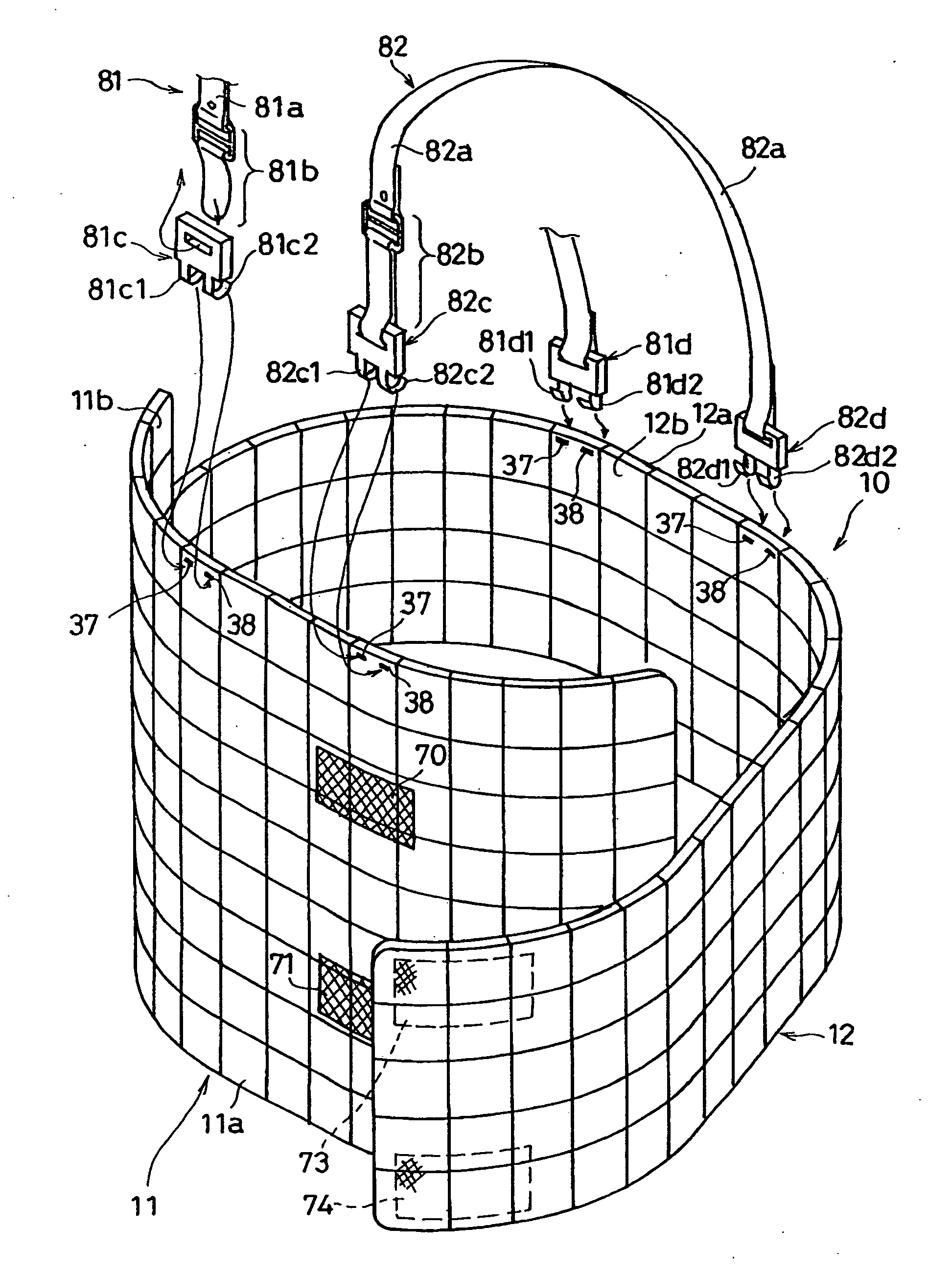
[0049] A stab proof vest (a stab proof jacket) 10 according to the present invention is used for protecting a wearer against an attacker (criminal) possessing a sharp object such as a knife. The stab proof vest 10 comprises elements (rectangular elements) 20 which are coupled vertically and horizontally. The first embodiment of the present invention will be hereinafter described in detail with reference to the accompanying drawings.
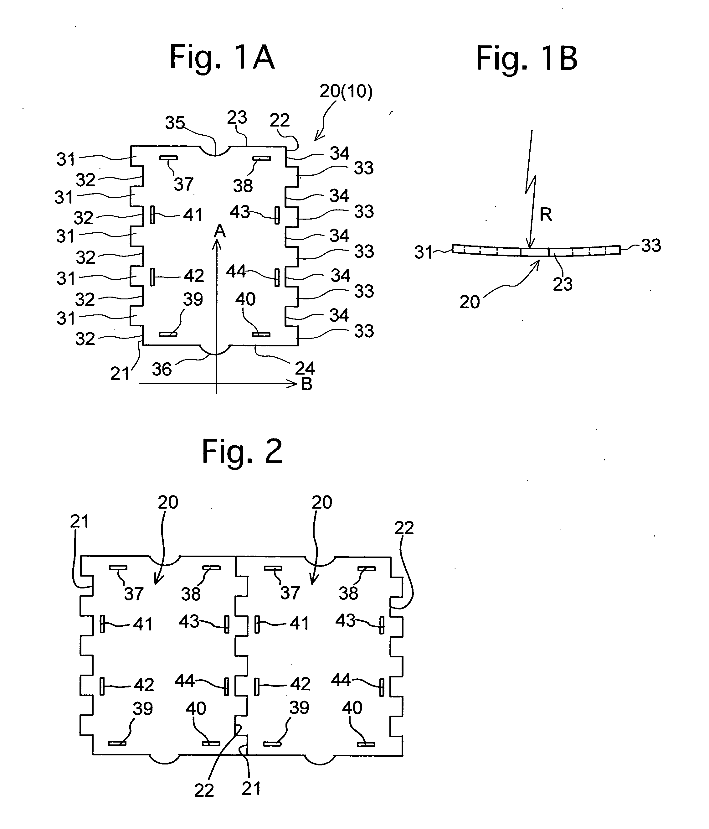
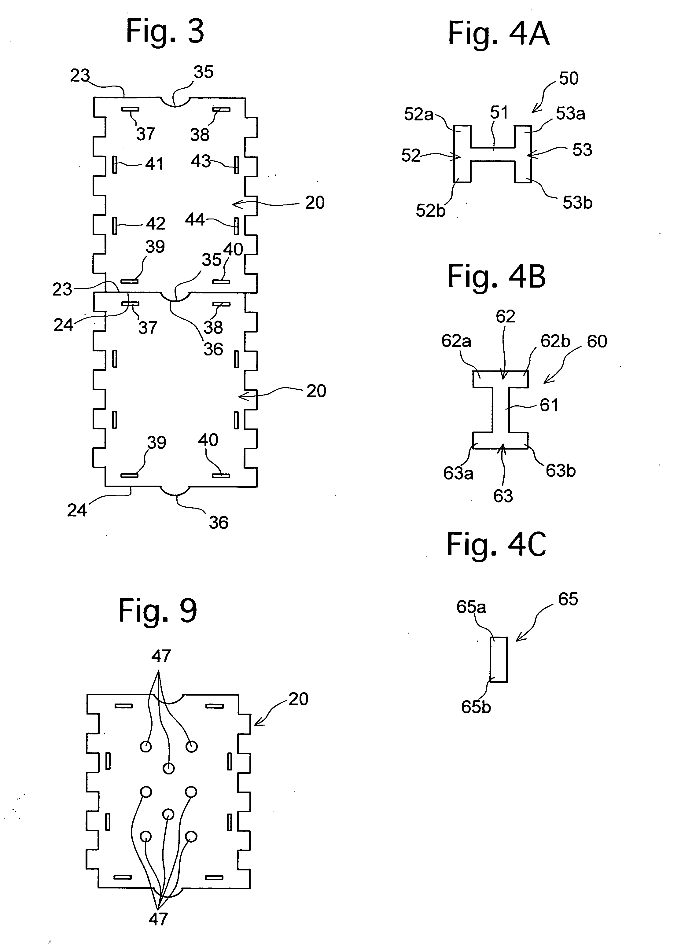
[0050]FIGS. 1A and 1B show an element 20 (of the stab proof vest 10 shown in FIG. 7). The element 20 is an approximately rectangle-shaped stainless steel plate which has been press-formed. According to an experiment carried out by the inventor of the present invention, even when the element 20 having a thickness of 0.8 mm is stabbed with great force using a knife, the tip of the knife does not penetrate the element 20. It is apparent from the experiment that the element 20 has high resistance to stabbing. On the other hand, it is...
second embodiment
[0076] (Second Embodiment)
[0077] A second embodiment of the present invention will be hereinafter described. In the second embodiment, identical members to the first embodiment are referred to the same reference numbers. In the second embodiment, the stab proof vest includes elements 90 and 120 shown in FIGS. 10A to 10D, in addition to the elements 20.
[0078] As shown in FIGS. 10A and 10B, the element 90 is a stainless steel plate having an approximately right-angled triangular shape which is press-formed. It is desirable for the thickness of the element 90 to be approximately 0.5 to 2 mm, and a range of 0.5 to 1 mm is more desirable. When the thickness of the element 90 is within the above-mentioned range, the wearer can wear the stab proof vest between outerwear and underwear, or under the underwear.
[0079] Rectangular projections 103 are provided on a long side 92 of the element 90 along a vertical direction (in direction C of FIG. 10A). The rectangular projections 103 protrude o...
third embodiment
[0096] (Third Embodiment)
[0097] In the third embodiment, identical members to the first and second embodiments are referred by the same reference numbers.
[0098] In a stab proof vest 170 according to the third embodiment, as shown in FIG. 15, plate members 180 and 190 are provided for wearing on the front body portion and the back body portion, respectively. The plate members 180 and 190 are connected by connection members 200 and 210, each of which is constructed from the elements 20 coupled vertically and horizontally.
[0099] Each of the plate members 180 and 190 in the shape of an approximately rectangle is press-formed from stainless steel. It is desirable that the thickness of the plate members 180 and 190 is approximately 0.5 to 2 mm, as in the case of the element 20. A range of 0.5 to 1 mm is more desirable. Although the plate members 180 and 190 are made of stainless steel in this embodiment, the members can be made of, for example, aluminum, acryl resin, polycarbonate, CFRP...
PUM
 Abstract
Description
Claims
Application Information