Method and apparatus for remediating wastewater holding areas and the like

a technology for wastewater holding areas and methods, applied in water cleaning, filtration separation, separation processes, etc., can solve the problems of difficult complete remediation of lagoons, inconvenient cleaning, and relatively inconvenient cleaning, so as to reduce the impact of surrounding environment, reduce the impact of process costs, and reduce the effect of was

Inactive Publication Date: 2005-01-27
INFRASTRUCTURE ALTERNATIVES
View PDF38 Cites 8 Cited by
  • Summary
  • Abstract
  • Description
  • Claims
  • Application Information

AI Technical Summary

Benefits of technology

[0010] The present invention provides a cost effective, timesaving and environmentally sensitive method and apparatus for treating water, including removing sludge from wastewater holding areas and the like. The present method and apparatus permit the water holding area to be treated, without removing the same from service, thereby resulting in substantial cost savings. Minimum impact to the surrounding environments, reduced odor, and improved drying to minimize dewatered sludge removal are also aspects of the present invention.

Problems solved by technology

It has been found that when a conventional pump is used to remove sludge from a retention area, the pump normally removes only a small area or portion of the sludge, such that complete remediation of the lagoon is difficult due to the unique characteristics of the sludge.
However, such processes are relatively invasive, and not environmentally sensitive to the adjacent area.
Furthermore, the remediation process removes the lagoon from service, and undesirable odors often result from the long drying process, which typically requires turning over the sludge to achieve additional drying.
Such methods also are not particularly effective in thoroughly drying the sludge to achieve a minimum volume, so as to facilitate removal and deposit of the dewatered sludge.
The various sludge press and centrifuge systems are expensive to purchase, operate and maintain.

Method used


Image

  • Method and apparatus for remediating wastewater holding areas and the like
  • Method and apparatus for remediating wastewater holding areas and the like
  • Method and apparatus for remediating wastewater holding areas and the like

Examples


Embodiment Construction

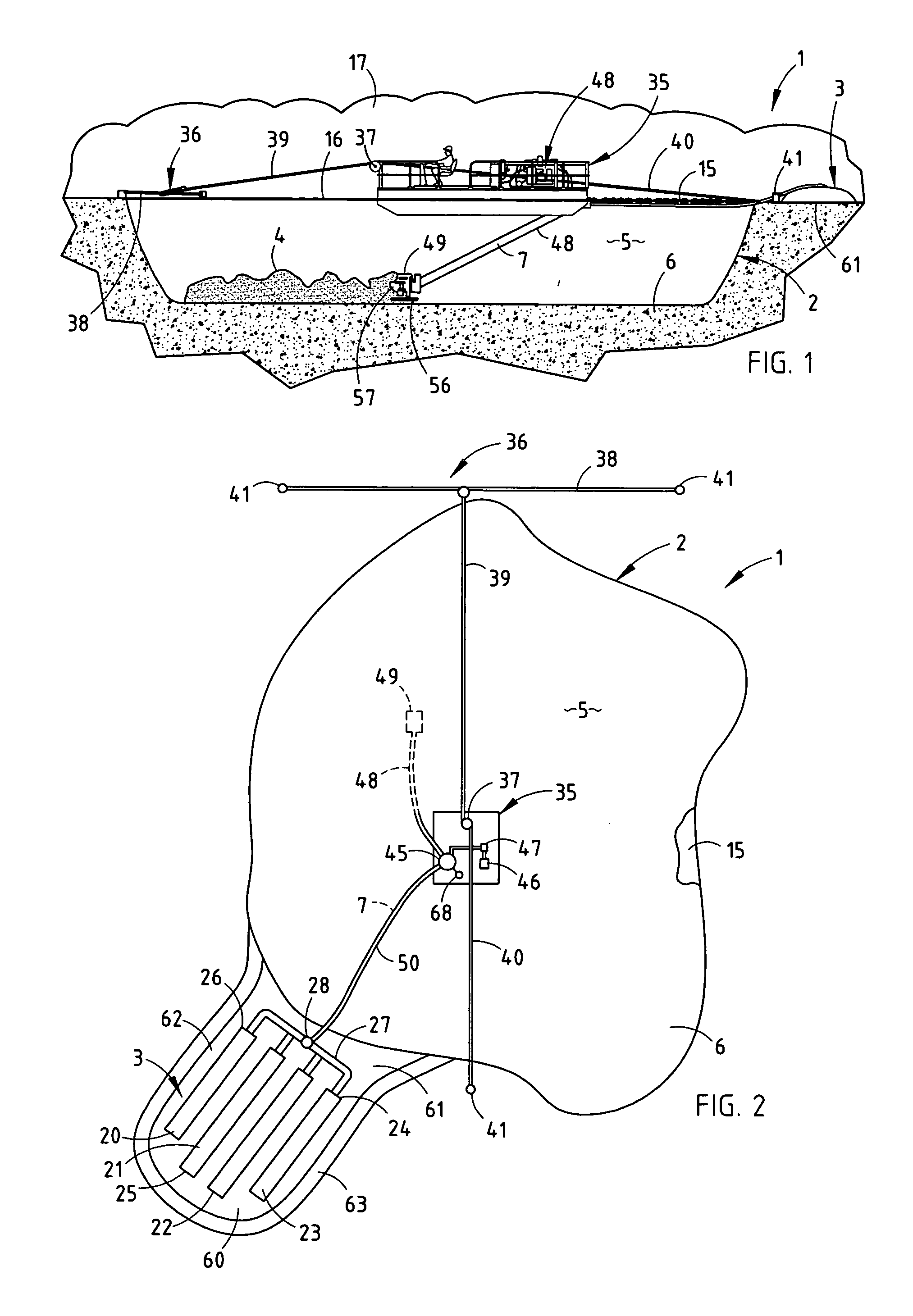
[0016] For purposes of description herein the terms “upper”, “lower”, “right”, “left”, “rear”, “front”, “vertical”, “horizontal” and derivatives thereof shall relate to the invention as oriented in FIGS. 1 and 2. However, it is to be understood that the invention may assume various alternative orientations and step sequences, except where expressly specified to the contrary. It is also to be understood that the specific devices and processes illustrated in the attached drawings, and described in the following specification, are simply exemplary embodiments of the inventive concepts defined in the appended claims. Hence, specific dimensions and other physical characteristics relating to the embodiments disclosed herein are not to be considered as limiting, unless the claims expressly state otherwise.

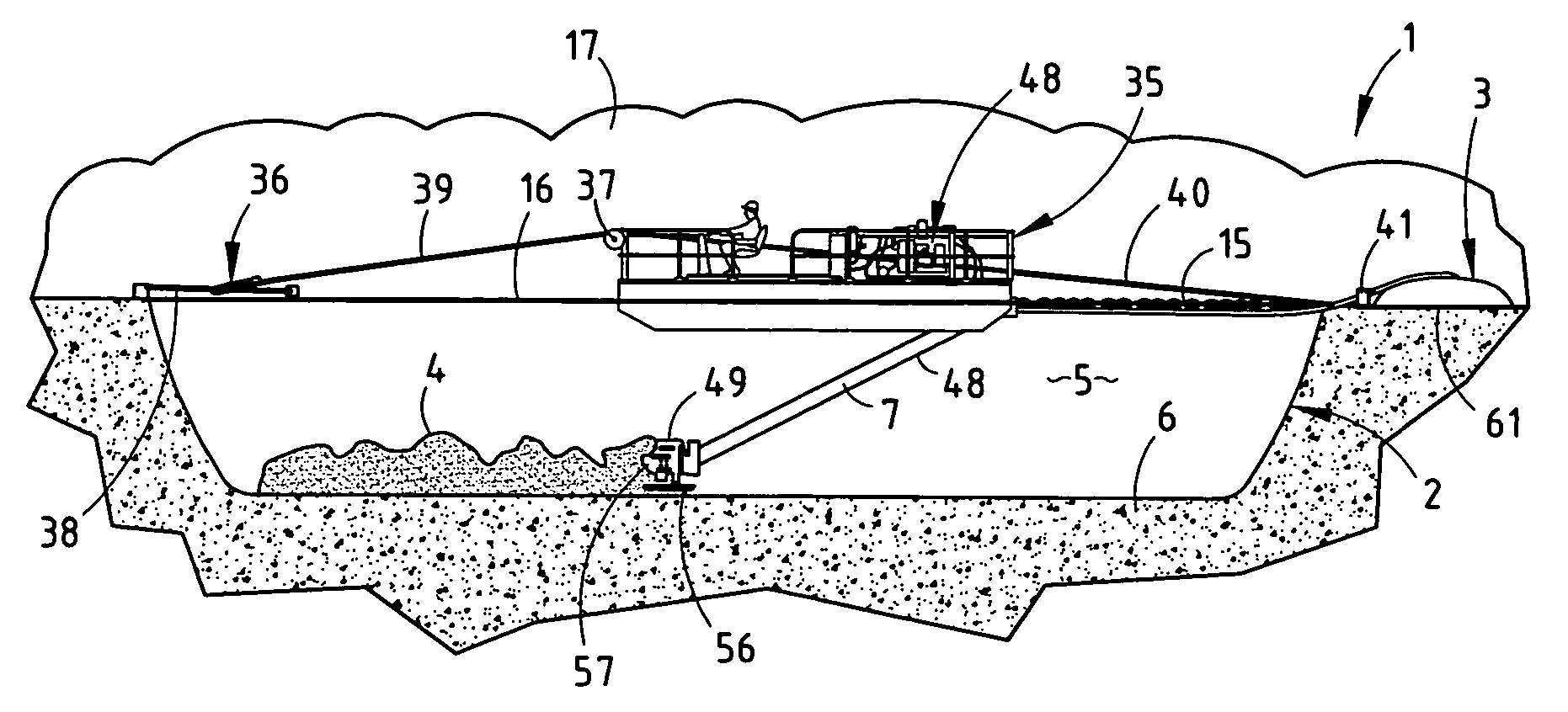
[0017] The reference numeral 1 (FIGS. 1-2) generally designates an apparatus for remediating water holding areas and the like, such as the illustrated pond or lagoon 2. Apparatus 1 inclu...


PUM

PropertyMeasurementUnit
diameteraaaaaaaaaa
gravitational forcesaaaaaaaaaa
distanceaaaaaaaaaa

Abstract

A method and apparatus for remediating waster water holding areas and the like includes a closed, foraminous dewatering membrane that is positioned adjacent to the wastewater holding area. Sludge and adjacent water on the bottom of the wastewater holding area are pumped in the form of a sludge slurry into the interior of the dewatering membrane. The water is removed from the sludge slurry by allowing gravitational forces to flow water through the dewatering membrane. The dewatering membrane is then opened, and the dewatered sludge is removed for depositing at an appropriate site.

Description

BACKGROUND OF THE INVENTION [0001] The present invention relates to water treatment, and in particular to a method and apparatus for remediating wastewater holding areas and the like. [0002] There have been developed over the years many different systems and devices for remediating wastewater holding areas, such as lagoons, ponds, holding vessels, basins, and other similar structures. Because of ecological considerations, research and development for feasible and economical solutions for cleaning up or remediating wastewater and other types of contaminated water have been greatly accelerated. [0003] The modern treatment of domestic wastewater through biological means results in a residual byproduct comprised mostly of bacterial cell material and inert debris. A common practice in the treatment of domestic wastewater is to utilize large holding vessels, also known as lagoons, to provide the necessary detention time and environmental conditions to complete the treatment process. Clear...

Claims


Application Information

Patent Timeline
Patent Type & Authority Applications(United States)
IPC IPC(8): B01D29/27C02F1/52C02F11/12C02F11/131C02F11/147
CPCB01D29/27C02F11/14C02F11/12C02F1/52C02F11/131C02F11/147
Inventor KELLER, ROBERT A.CRETENS, WILLIAM J.DEPUYDT, KENT T.TRIERWEILER, DANA J.JOHNSON, RUSSELL D.WICKOREN, DEAN R.
Owner INFRASTRUCTURE ALTERNATIVES
Why Eureka
Try Eureka