
Storage system

a storage system and storage system technology, applied in the field of storage systems, can solve the problems of difficult to maintain the response speed to the write request becomes approximately equal, and the throughput performance of the storage system is difficult to maintain

Active Publication Date: 2005-01-27
GOOGLE LLC
View PDF12 Cites 32 Cited by
  • Summary
  • Abstract
  • Description
  • Claims
  • Application Information

AI Technical Summary

Benefits of technology

[0010] An object of the present invention is to provide a storage system capable of having a large-scale configuration for maintaining a write access response speed and reliability upon the occurrence of a failed cache and its control method.

Problems solved by technology

However, the reliability is maintained by the write through control, but the abovementioned advantage of the cache memory is lost, with the result that, even if the cache memory is possessed, the response speed to the write request becomes approximately equal to the case where the cache memory is not possessed.
Therefore, as the configuration scale of the storage system becomes large, an access is concentrated on the cache memory or information for managing the cache memory, thereby entailing a problem that a throughput performance of the storage system is difficult to be maintained only by having the cache memory.
Further, the problem same as the abovementioned one is applied to the case of maintaining the reliability of the storage system and write performance in a case where the failure occurs in the cache memory.
Specifically, the technique disclosed in the aforesaid Japanese laid-open publication number 2001-344154 unifiedly utilizes the cache memory, so that as the configuration scale of the storage system becomes large, an access is concentrated on the cache memory or information for managing the cache memory upon the occurrence of the failure in the cache memory, thereby entailing a problem that a throughput performance of the storage system is difficult to be maintained only by having the cache memory, and consequently, it is difficult to provide both the enlargement of the configuration scale and the reliability upon the occurrence of the failure.

Method used


Image

  • Storage system
  • Storage system
  • Storage system

Examples


Embodiment Construction

[0036] An embodiment of the present invention will be explained hereinbelow with reference to drawings. It is needless to say that the present invention is not limited to the embodiments described hereinbelow.

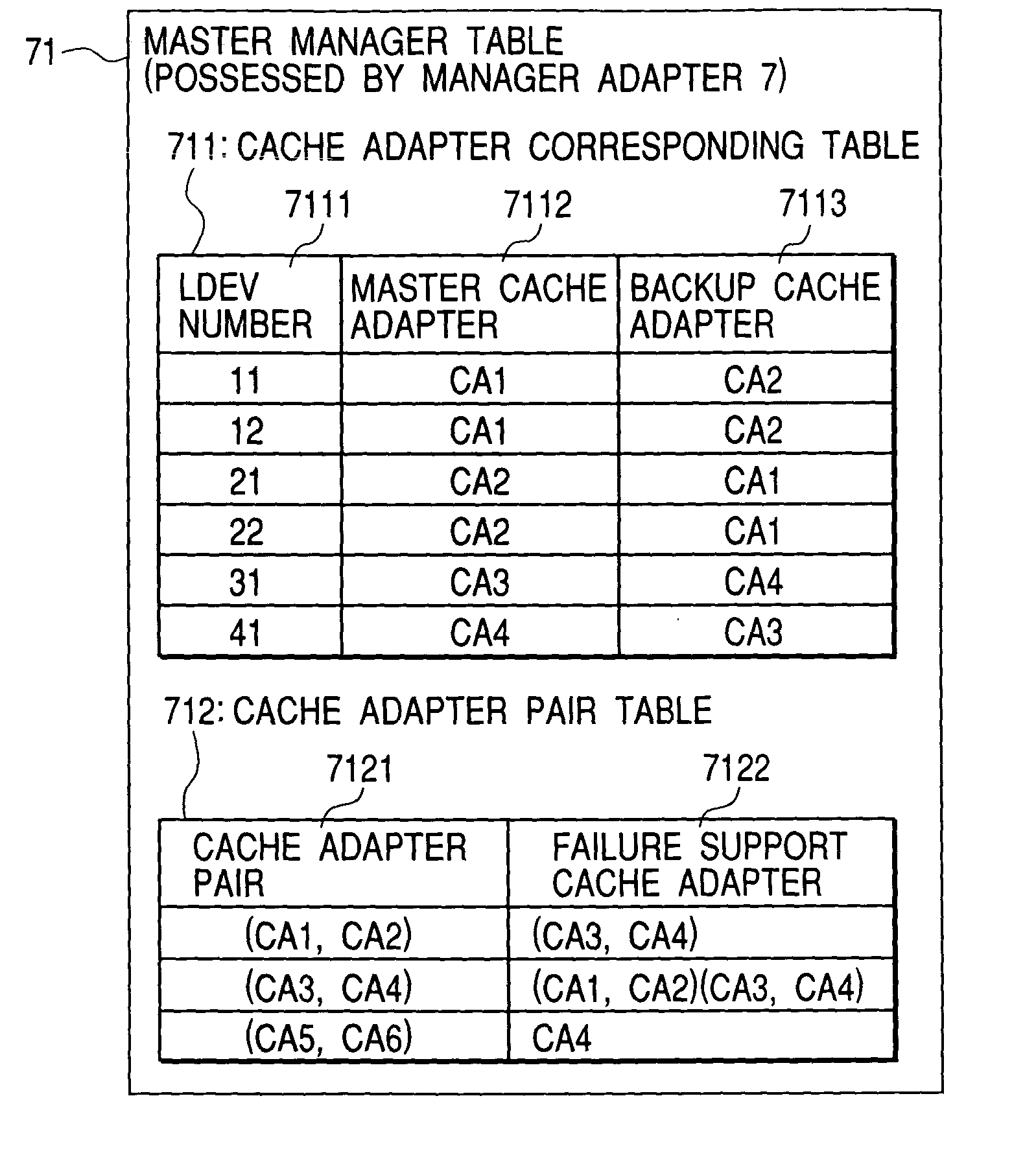
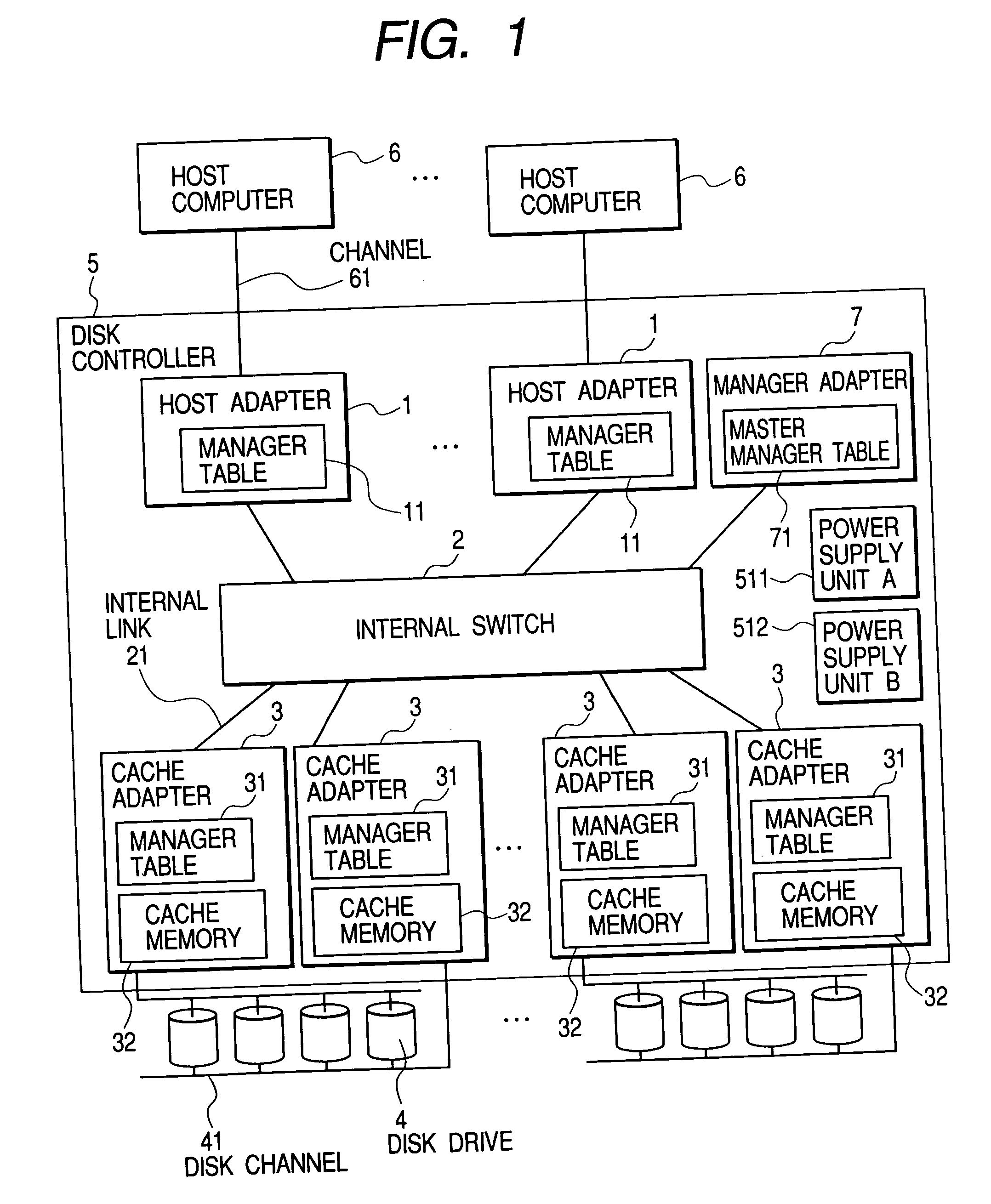
[0037]FIG. 1 is a view showing a first embodiment of a storage system to which the present invention is applied. The storage system has a disk controller 5 and plural disk drives 4. It is to be noted that the disk drive 4 means a storage unit having a non-volatile storage medium such as a hard disk drive, CD, DVD or the like. The disk controller 5 is connected to a host computer 6 via a communication line (hereinafter referred to as “channel”) 61. Further, the disk controller 5 and the disk drives 4 are connected to each other via a communication line (hereinafter referred to as “disk channel”) 41. The host computer 6 sends or receives data to or from the disk drives 4 via the channel 61, the disk controller 5 and the disk channel 41.

[0038] A protocol such as, for example, SC...


PUM


Abstract

The present invention provides a storage system capable of having a large-scale configuration for maintaining a write access response speed and reliability upon an occurrence of a failed cache and its control method. Plural clusters that control a disk drive connected thereto and have a cache memory are connected to one another through a cross coupling network, and write data in the cache memory of another cluster is mutually made redundant in the cache memories in two clusters that jointly use the same disk drive. When a failure occurs in the cache memory, the cluster that uses the disk drive jointly with the cluster having the cache memory in which the failure occurs performs processing for getting access to the disk drive performed by the cluster having the cache memory in which the failure occurs, and the other normally-operated cluster is caused to perform to only make redundant the write data in the cache memory in its cluster.

Description

BACKGROUND OF THE INVENTION [0001] The present invention relates to a storage system provided with a cache memory and a control method of the cache memory. [0002] As a technique for improving a performance of a storage system having plural storage units (hereinafter referred to as just “storage system”), there has been well-known a technique of introducing a volatile semiconductor memory section (hereinafter referred to as “cache memory”) to the storage system. [0003] With respect to a data write request, a storage system having a cache memory returns a response of completing the write to a computer that requires the data write at the time when the data is written in the cache memory (hereinafter referred to as just “computer” or “host computer”), while asynchronously writes data to a storage unit. Since the speed of writing data to the cache memory is faster than the storage unit (a disk drive or the like here), the storage system can return the response to the host computer with h...

Claims


Application Information

Patent Timeline
Patent Type & Authority Applications(United States)
IPC IPC(8): G06F3/06G06F12/08G06F11/20G06F12/16
CPCG06F11/1666G06F12/0866G06F11/2071G06F11/20
Inventor NAKAMURA, SHUJISHIMADA, KENTARO
Owner GOOGLE LLC
Learn More