Cement float

a cement float and cement technology, applied in the field of cement floats, can solve the problem of not being able to accept cement floats

Inactive Publication Date: 2005-02-03
SCHLUMBERGER TECH CORP
View PDF11 Cites 15 Cited by
  • Summary
  • Abstract
  • Description
  • Claims
  • Application Information

AI Technical Summary

Benefits of technology

[0004] In accordance with a broad aspect of the present invention, there is provided a cement float for use in a wellbore tubing string includes: a mandrel including a first end, a second end, a bore extending from the first end to the second end including a fluid flow control device therein and outer side surfaces defining a tapering outer diameter from the first end of the mandrel to the second end; an outer lock sleeve including an outer surface and a sleeve bore through the sleeve, the outer lock sleeve retained at least about the outer side surfaces of the mandrel with the mandrel extending through the sleeve bore, the sleeve bore having a taper to complement and be coactable with the tapering outer diameter of the mandrel outer side surfaces and the sleeve bore and the mandrel outer side surfaces defining interfacing surfaces therebetween, the sleeve being expandable radially outwardly by driving the mandrel against the taper of the sleeve bore to place the cement float in an anchored position in the tubing string with the outer lock sleeve wedged between the mandrel and the tubing string, the outer lock sleeve and the mandrel being formed over at least a portion of their interfacing surfaces to be frictionally and/or mechanically interactive to provide self locking against sliding movement therebetween that would dislodge the cement float from its anchored position.
[0005] In accordance with ...

Problems solved by technology

Sometimes however, the profile in the profile nip...

Method used


Image

  • Cement float
  • Cement float
  • Cement float

Examples


Embodiment Construction

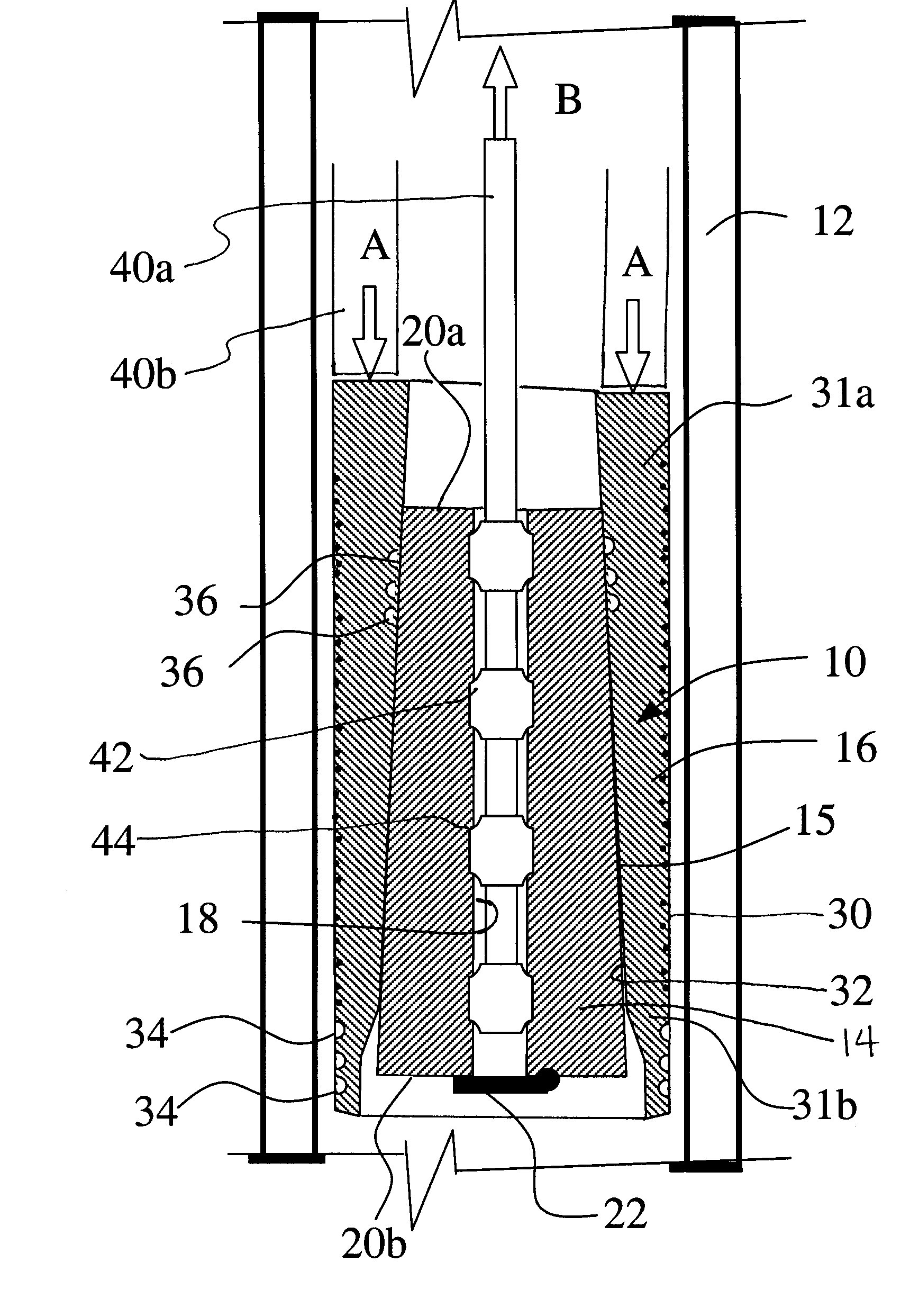
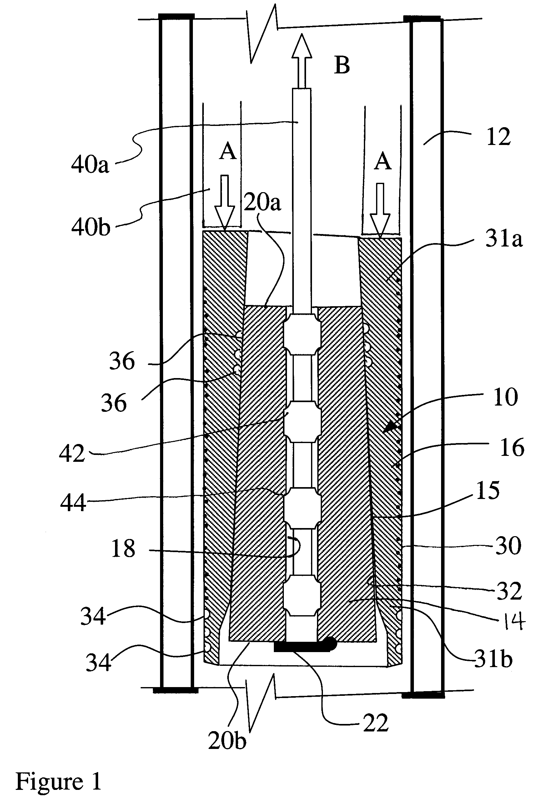
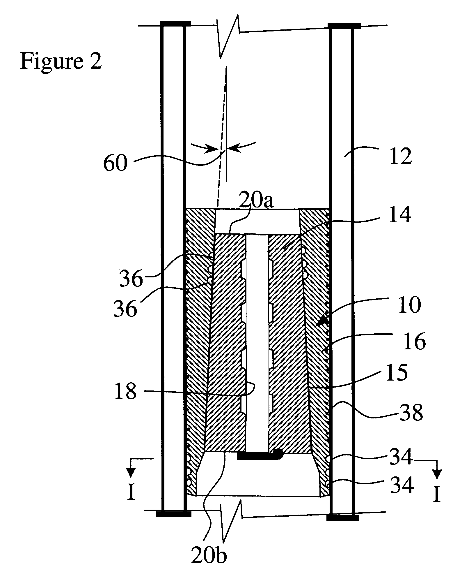
[0010] Referring to the drawings, a cement float 10 is shown which can be installed in a wellbore tubing string, such as a casing string, a portion of which is shown at 12. Once installed, the cement float may permit fluid flow downwardly therethrough, but seal against reverse flow upwardly therepast. In a cementing operation, the cement float is installed to permit cement to be pumped down through the wellbore liner and upwardly through the annulus liner / wellbore annulus and will maintain the cement in the annulus, by sealing against reverse flow (called U-tubing) until the cement sets.

[0011] The cement float may include a center mandrel 14 including outer side surfaces 15 and an outer lock sleeve 16, which may encircle the mandrel and may be retained by frictional engagement or mechanical engagement on at least the outer side surfaces of mandrel 14.

[0012] Mandrel 14 may include a bore 18 extending between its ends 20a and 20b. A fluid flow control device 22 such as a plug, shear...


PUM


Abstract

A cement float for use in a wellbore tubing string includes: a mandrel including a first end, a second end, a bore extending from the first end to the second end including a fluid flow control device therein and outer side surfaces defining a tapering outer diameter from the first end of the mandrel to the second end; an outer lock sleeve including an outer surface and a sleeve bore through the sleeve, the outer lock sleeve retained at least about the outer side surfaces of the mandrel with the mandrel extending through the sleeve bore, the sleeve bore having a taper to complement and be coactable with the tapering outer diameter of the mandrel outer side surfaces and the sleeve bore and the mandrel outer side surfaces defining interfacing surfaces therebetween, the sleeve being expandable radially outwardly by driving the mandrel against the taper of the sleeve bore to place the cement float in an anchored position in the tubing string with the outer lock sleeve wedged between the mandrel and the tubing string, the outer lock sleeve and the mandrel being formed over at least a portion of their interfacing surfaces to be frictionally and/or mechanically interactive to provide self locking against sliding movement therebetween that would dislodge the cement float from its anchored position. A method for setting the cement float is also disclosed.

Description

CROSS REFERENCE TO RELATED APPLICATIONS [0001] The present application claims priority from U.S. Provisional Application No. 60 / 477,787, filed Jun. 12, 2003.BACKGROUND OF INVENTION [0002] The present invention relates to a cement float for wellbore operations. [0003] In casing drilling the casing string is used both as the drill string and the borehole liner. When drilling is complete, a cement float must be run in through the casing string and is generally landed in a profile nipple, which is a sub in the original casing string that contains an annular groove called a profile. Sometimes however, the profile in the profile nipple is damaged so that it cannot accept a cement float. In such a case and in other instances when the use of a profile nipple is not desirable, a cement float is required that does not rely on the existence of a profile. SUMMARY OF INVENTION [0004] In accordance with a broad aspect of the present invention, there is provided a cement float for use in a wellbor...

Claims


Application Information

Patent Timeline
IPC IPC(8): E21B21/10E21B23/01E21B33/00E21B33/14
CPCE21B21/10E21B33/14E21B23/01
Inventor WARREN, TOMMY M.ANGMAN, PER G.
Owner SCHLUMBERGER TECH CORP
Why Eureka
Try Eureka