
Combination lock washer and spindle bearing assembly

a technology of locking washer and spindle bearing, which is applied in the direction of threaded fasteners, screws, bearing unit rigid support, etc., can solve the problems of multiple components, time-consuming installation, and limited adjustment positions

Active Publication Date: 2005-02-03
DANA HEAVY VEHICLE SYSTEMS GROUP LLC
View PDF41 Cites 77 Cited by
  • Summary
  • Abstract
  • Description
  • Claims
  • Application Information

AI Technical Summary

Benefits of technology

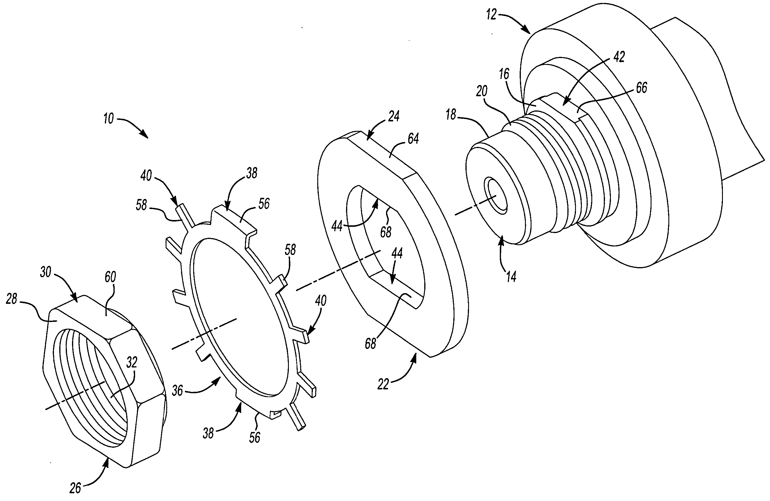
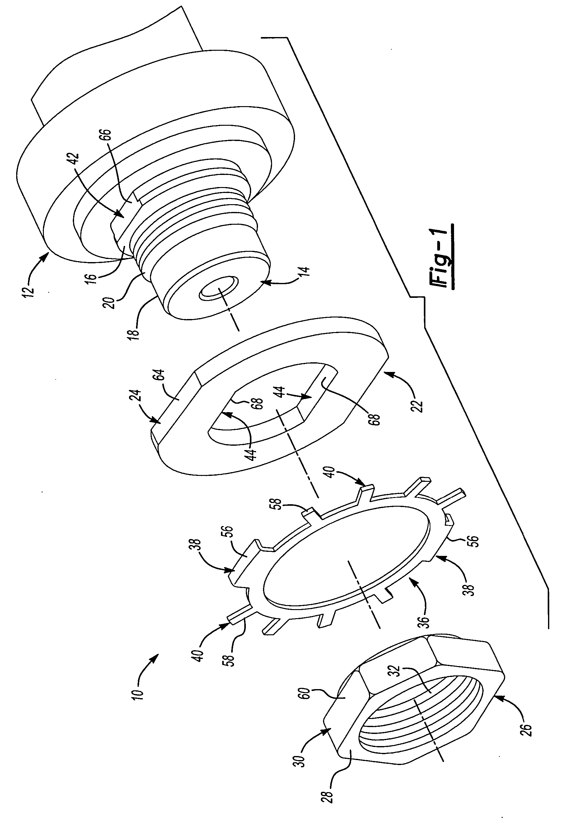
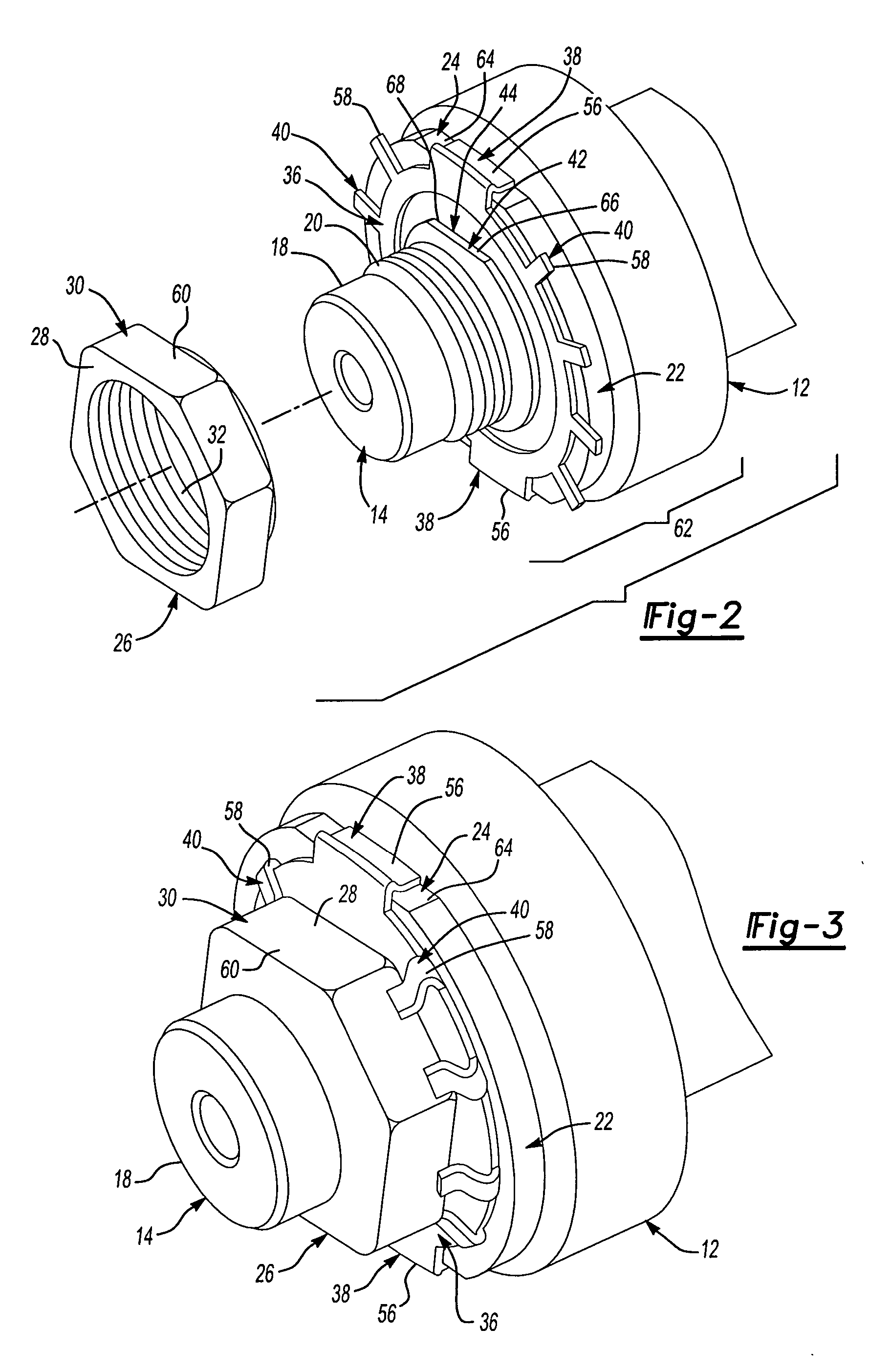
[0006] An apparatus in accordance with the present invention provides for a combination lock washer and spindle bearing assembly. The combination lock washer and spindle bearing assembly is provided to include a spindle, thrust washer, lock washer and nut, the lock washer simultaneously locks an inner thrust washer and an outer spindle nut. The thrust washer, lock washer and nut may be oriented at any angle relative to one another allowing for infinite adjustment positions. The spindle includes a spindle shoulder and a spindle end extending outward from the spindle shoulder with an uninterrupted thread configuration. The thrust washer is disposed about the spindle shoulder and has at least one outer retaining feature. The nut is disposed about the uninterrupted thread configuration and includes a nut body with at least one nut retaining feature and an inner circumferential shoulder extending from the nut body in direct contact with the thrust washer forming a pocket between the thrust washer and nut body. The lock washer is disposed about the inner circumferential shoulder and is retained within the pocket between the thrust washer and nut body. The lock washer further has at least one washer extension corresponding to and engaging each outer retaining feature of the thrust washer, and at least one nut extension corresponding to and engaging each nut retaining feature of the nut.

Problems solved by technology

However, these designs may provide for limited adjustment positions, may not permit assembly of multiple components with standard socket installation sizes, may be time consuming to install, or may have a keyway in the thread providing for lower thread torque limitations.

Method used


Image

  • Combination lock washer and spindle bearing assembly
  • Combination lock washer and spindle bearing assembly
  • Combination lock washer and spindle bearing assembly

Examples


Embodiment Construction

[0015] Referring now to the drawings wherein like reference numerals are used to identify identical components in the various views, FIGS. 1 and 4 illustrate a portion of a vehicle having a combination lock washer and spindle bearing assembly 10 in accordance with various embodiments of the present invention. A combination lock washer and spindle bearing assembly 10 is provided to include a spindle 12, thrust washer 22, lock washer 36 and nut 26 which may be oriented at any angle relative to one another allowing for infinite adjustment positions, at the same time the lock washer 36 of the present invention prevents relative rotation between the spindle 12, thrust washer 22, lock washer 36, and nut 26.

[0016] An embodiment of the present invention provides a spindle 12 including a spindle shoulder 16 and a spindle end 18 extending outward from the spindle shoulder 16 with an uninterrupted thread configuration 20. The thrust washer 22 is disposed about the spindle shoulder 16 and has ...


PUM


Abstract

The present invention relates to a connection between a spindle and a bearing assembly to retain the bearing assembly on the spindle. A combination lock washer and spindle bearing assembly is provided to include a spindle, thrust washer, lock washer and nut in which the lock washer simultaneously locks the inner thrust washer and an outer spindle nut. According to the present invention, the thrust washer, lock washer and nut may be oriented at any angle relative to one another allowing for infinite bearing adjustment positions.

Description

BACKGROUND OF THE INVENTION [0001] 1. Field of the Invention [0002] The present invention relates to a vehicle wheel end system, and more particularly, to the connection between a spindle and a spindle bearing including a lock washer to simultaneously lock an inner thrust washer and an outer spindle nut. [0003] 2. Discussion of Related Art [0004] Generic lock washers are known in the art. Some lock washers have an inwardly extending tang to engage a groove in a shaft to which the washer is mounted. Other washers have tabs to engage a nut to prevent rotation. Still other washers have a longitudinally extending pin to engage a recess in an adjacent nut to prevent rotation. However, these designs may provide for limited adjustment positions, may not permit assembly of multiple components with standard socket installation sizes, may be time consuming to install, or may have a keyway in the thread providing for lower thread torque limitations. None of the prior art lock washers or lock w...

Claims


Application Information

Patent Timeline
IPC IPC(8): F16B39/10F16C35/063
CPCF16B39/103F16C35/063F16B39/108F16C25/06F16C2226/60
Inventor SLESINSKI, STEVEMOREAU, JEFFMOSES, DAVELYON, TOM
Owner DANA HEAVY VEHICLE SYSTEMS GROUP LLC
Learn More